Bal-tec™ Home All Vee Blocks
All Veeblocks and Canoespheres
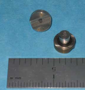
Teeny Tiny Vee Block
Part Number: VB-187-CPM. For balls from 3/16" (.1875", 4.76mm) through 1/4" (.25", 6.35mm).
| Downloads | ||
|---|---|---|
| Solidworks | IGES | |
Building a teeny tiny vee block for Kinematic applications presents some unusual challenges. The design chosen uses the well-proven cylindrical post-mounted vee block. The post is used to both locate and clamp the vee block in position. The cylindrical post is precision ground to .250 inches.
The flange adjacent to the post is ground flat and square to the post. The post is drilled and tapped for a 4-40 hold down screw. After precision grinding the flat prismatic faces of the tiny vee block, these faces are precision lapped. The vee block is constructed from a high chrome, high carbon, Martensitic stainless steel that is hardened to 58 HRC minimum. This ultra fine-grained material provides excellent repeatability with good fret resistance.
This very small size component will match balls from just under three sixteenth's (3/16" ) of an inch ( 4.8 mm ) to just over one quarter inch ( 1/4" ) ( 6.4 mm ) diameter. Our part number on this item is VB-187-CPM.
See here for Vee Block prices.
A Mid Size Vee Block
Cylindrical Post Mounted — Part Number: VB-375-CPM, For 5/16" ( 0.3125", 7.94 mm ) through 1/2" ( 0.50", 12.7 mm ) Balls
| Downloads | ||
|---|---|---|
| Solidworks | IGES | |
This device is designed to accept spheres from five sixteenths of an inch 5/16", 0.3125" ( 7.9 mm ), three eighths, 3/8", 0.375" of an inch ( 9.5 mm) is nominal, to one half of an inch, 1/2", 0.50" (12.7 mm) in diameter. It is our part number, VB-375-CPM.
The cylindrical mounting post is precision ground to three eighths (3/8") of an inch ( 0.375", 9.5 mm ) diameter, tolerance plus 0.0000 inches or minus 0.0005 inches (.013 mm). This post is one quarter of an inch( 1/4", 0.250", 6.35 mm ) long. The flat flange adjacent to the post is precision ground flat and square to the post. The included angle of this vee block is 90 degrees.
This device is designed for universal mounting from either the front or from behind. The major diameter of this Vee Block is three quarters (3/4") of an inch (19 mm). The flat faces of this device are precision ground with the face of the grinding wheel, not the periphery. The resulting crisscross pattern breaks up the lay of the surface texture to give this couple far superior repeatability.
There is a hole drilled through the center of the post that is tapped to accept a # 10-24 hexagon socket head cap screw, a threaded fastener. This allows the vee block to be clamped down solidly from the rear end. This same hole is counterbored from the front, which allows it to be clamped down from the front by a #6 hexagon socket head cap screw. This vee block is constructed from a very high chrome, high carbon, Martensitic stainless steel. This ultra fine-grained material is hardened to a 58 HRC minimum. These Vee Blocks are highly magnetic.
See here for Vee Block prices.
Surface Mounted Vee Block
Part Number: VB-375-SM, For 5/16" (.3125", 7.94mm) through 1/2" (.500", 12.7mm) balls.
| Downloads | ||
|---|---|---|
| Solidworks | IGES | |
- This device is designed to accept spheres from five sixteenths of an inch ( 5/16 inch ) ( 0.3125 inch ) [ 7.9mm ] to one half inch ( 1/2 inch )( 0.5 inch ) [ 12.7 mm ] diameter. Three eights of an inch ( 0.375 inch ) [ 9.5mm ] is the nominal diameter.
- This is our Part # VB-375-SM.
- The flat mounting surface on the back side of this part is a precision flat lapped annulus.
- The included angle of this Vee Block is 90 degrees.
- The major diameter of this Vee Block is three quarters of an inch ( ¾ inch )( 0.75 inch ) [ 19mm ].
- The flat faces of the vees of this device are precision ground on a special custom built machine with the face of the grinding wheel, not the periphery. The resulting crisscross pattern breaks up the lay of the surface texture to give this couple far superior repeatability.
- This device is designed for surface mounting without any protrusions on the back surface. In order to achieve greater rigidity the outside, three quarter inch (19mm) diameter can be epoxy glued into a shallow counterbore.
- The hold down arrangement on this device consists of two # 6-32 threaded holes that are precision spaced 1/2 inch, (0.5 inch) [12.7 mm] apart.
- The VB-375-CPM has a center through hole that is one eight of an inch ( 1/8 inch ) (0.125 inch) [3.2mm] diameter.
- This vee-block is constructed from a very high-chrome, high-carbon, martensitic stainless-steel. This ultra fine-grained material is hardened to a 58 HRC minimum.
Mid Sized Surface Mounted Vee Block
For 5/8" ( 0.625", 15.875 mm ) through 1" ( 25.4 mm ) Balls — Part Number: VB-75-SM


| Downloads | ||
|---|---|---|
| Solidworks | IGES | |
This component, also known as a Standard V Block, ( Part No. VB-75-SM, made from Hardened Stainless Steel ) is designed primarily for high load carrying kinematic couplings and precision tooling applications. The contact area between a sphere and the precision ground flat surfaces of the Vee block is greater than that between a sphere and two cylinders. This gives the Vee block a much higher load carrying capacity than the two cylinders.
This Vee block component is designed for flat surface mounting to the kinematic or tooling platform. The precision flat lapped base of this component is held in solid contact with the top surface of the platform by two cap screws. It can be clamped down from either the front or from the rear.
Two through holes are provided, one at each end of the Vee. They are tapped for #10 x 32 screws. Using these tapped holes, the Vee block can be pulled down solidly against the platform from behind. If front mounting is desired, the Vee block can be held solidly against the platform by two #6 round head screws. These screws will pass through the center of the same tapped holes but from the front surface.
There is a 1/2 inch diameter shallow counterbore in the flat base of this component. The remaining annular ring provides a very stable locating surface. This counterbore provides a recess that will hold adhesive if the component is glued down. These Vee blocks are made of very fine grained, high chrome, high carbon, stainless steel that is hardened to 58 HRC and ultra cold cycled for long term dimensional stability.
The 90 degree ground faces of the Vee block are tangent to any ball diameter from 5/8" ( 0.625 inch, 15.875 mm) to 1.00 inch (25.4 mm), with the ideal size being 3/4" ( 0.750", 19.05 mm).
See here for Vee Block prices.
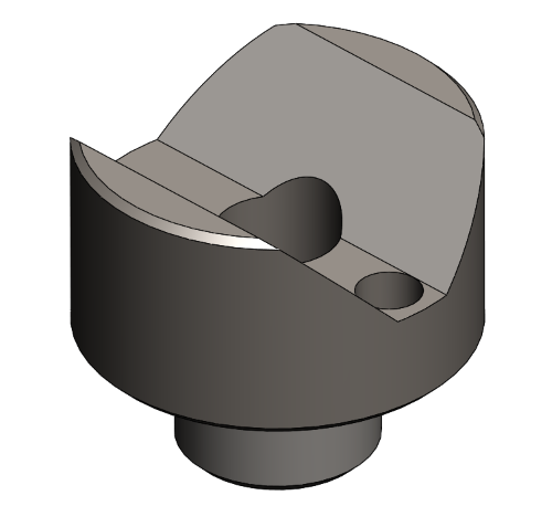
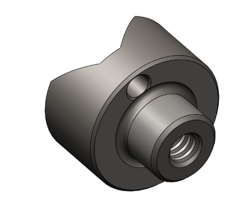
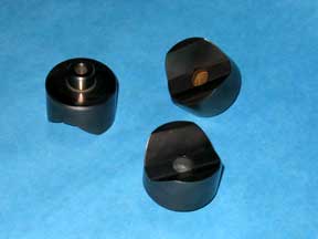
Most Popular Cylindrical Post Mounted Vee Block
Part No. VB-75-CPM, For 5/8" ( 0.625", 15.875 mm ) through 1.0" ( 25.4 mm ) Balls
| Downloads | ||
|---|---|---|
| Solidworks | IGES | |
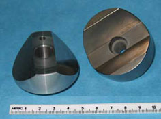
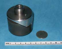
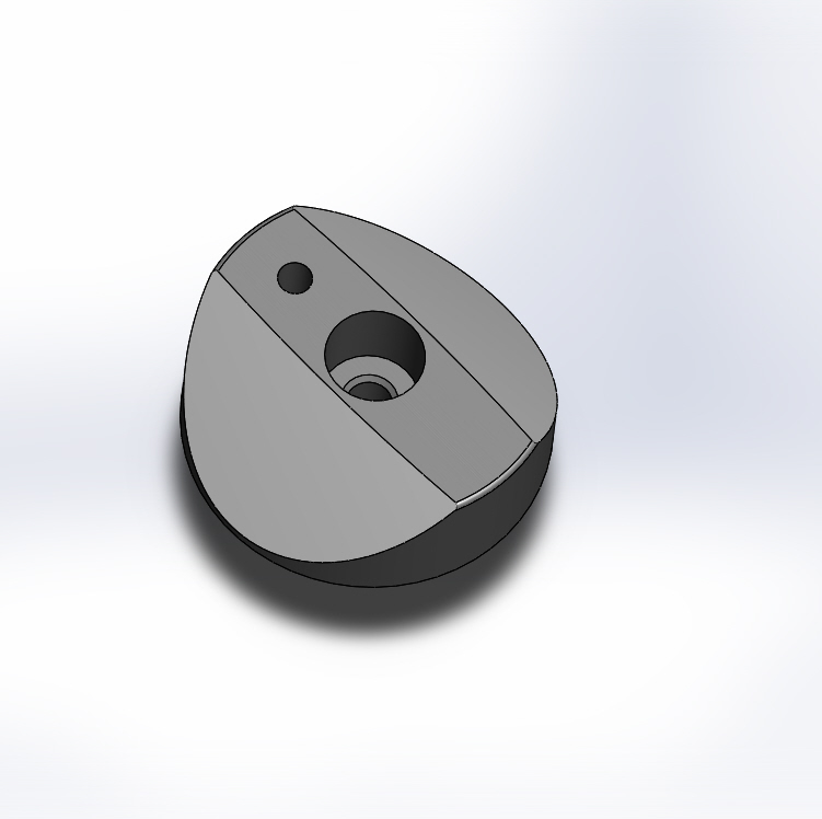
This kinematic Vee Block component (also known as Cylindrical Boss Mounted Vee Block ) is designed for both high load carrying capacity and easy installation. Because the contact area between a sphere and the precision ground flat surfaces of the Vee block is greater than that between a sphere and two cylinders, this Vee block has a much higher load carrying capacity. Precise location of this component is achieved through a precision ground cylindrical post. The flange adjacent to the cylinder is also ground flat.
This design facilitates the accurate installation of this component without the use of precision machine tools. The desired mounting is simply scribed on the surface of one of the kinematic or tooling platforms with a compass. This circle is then divided into three equal cords and the intersections are center punched. The top and bottom platforms are clamped together. Three holes are then drilled and reamed, through both of the platforms. This can be done on a drill press or even with a hand drill. With the three .500 inch ( 12.7mm ) diameter holes now drilled through both platforms three of the cylindrical post mounted Vee blocks can be mounted on one platform, and three of the part number 75 B-T balls can be mounted on the other to form a perfect kinematic system.
These Vee blocks are made of very fine grained high chrome, high carbon, stainless steel that is hardened to 58 HRC and ultra cold cycled for long term dimensional stability. The 90 degree precision ground faces of the Vee block are tangent to any ball diameter from 5/8"(0.625 inch, 15.87mm) to 1.00 inch (25.4 mm), with the ideal size being 3/4" (0.750 inch, 19.05mm). To orient the Vee and to prevent any rotation, there is one 0.093 inch (2.3622 mm) diameter dowel pin hole machined through the outside edge of the flange.
These Vee blocks can be held in place from either the front or the rear. They can be solidly bolted down from the front surface by a #10 hexagon socket head cap screw. The head of this cap screw is recessed in a counterbore to avoid contact with the ball. For back surface installation, use a #1/4-20 hexagon socket head cap screw. The Vee can also be pulled down from behind by a 1/4 inch-20 bolt screwed into the threaded hole in the center of the cylindrical post.
| Part # | Description | Price | Purchase |
|---|---|---|---|
| SP-VB-45 | VEE BLOCK, 45 DEGREES, SPLIT | $24.23 | |
See also here for Vee Block Prices
Cylindrical Post Mounted Kinematic
Giant Vee Block — for 1 1/4" ( 1.25", 31.75 mm ) through 2.0" ( 50.8 mm ) Balls
| Downloads | ||
|---|---|---|
| Solidworks | IGES | |
The large cylindrical post-mounted vee block (our part number VB-2000-CPM) is a very heavy load-carrying device. It is built around a two-inch diameter cylindrical envelope. The cylindrical mounting post is precision ground, to three quarters of an inch (3/4" 0.750", 19.05 mm) in diameter, tolerace plus 0.0000 inches or minus 0.0005 inches (.013 mm) and is three quarters of an inch (3/4", 0.75", 19.05 mm) long. The adjacent flat flange is precision ground flat and square to the post.
This device is designed for universal mounting from either the front or from behind. The center of the post is drilled through and threaded to accept a M10 x 1.5 metric screw fastener. This can be used to hold it down from the rear. The drilled center hole of the vee block is counterbored in the front to accept a five-sixteenths ( 5/16" ) of an inch (7.9 mm) diameter socket head cap screw.
This arrangement can be used to clamp it down from the front. This device is compatible with load spheres from one and one quarter ( 1 1/4" ) of an inch (32 mm) to two-inch (51 mm) diameter. The included angle of this Vee Block is 90 degrees. The flat prismatic surfaces of this vee block are precision ground with the face of the grinding wheel not the periphery. This technique breaks up the lay of the surface texture and gives these vee blocks far superior repeatability.
These vee blocks are manufactured from a very high chrome, high carbon, Martensitic stainless steel. This ultra fine-grained material is hardened to 58 HRC minimum. These Vee Blocks are highly magnetic.
For a heavy load capability, see also "Canoe Sphere."
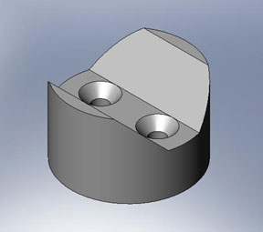
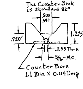
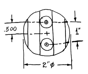
Giant Surface Mounted Kinematic Vee Block
VB-2000-SM, For 1 1/2" ( 1.5", 38.1 mm ), Balls through 2" ( 50.8 mm ) Balls
| Downloads | ||
|---|---|---|
| Solidworks | IGES | |
For very heavily loaded systems, this Vee block, ( V Block ) is fully compatible with our Canoe sphere (see our Kinematic catalog # 105B), to give it the ultimate in precision location, along with the highest load carrying capacity available.
This vee block is built on a two inch 2.0" (50.8 mm) diameter base. It has two threaded holes that are ( 5/16 inch, 0.312", 8 mm ) diameter with 18 threads per inch. They are spaced one inch ( 1.0", 25.4 mm ) apart so that the vee block can be fastened down from the back. These same through holes are counter sunk from the front so that two (1/4 inch, 0.250", 6.4 mm) flat head screws can be used to hold the vee blocks down from the front.
The bottom surface of this vee block is recessed to provide a shallow pocket that provides a strong glue line for holding the part down. The remaining annular ring, that is left around the bottom, is precision flat lapped, to provide the ultimate in stability, for locating this vee block.
For greater security, the 2-inch ( 50.8 mm ) outside diameter of this device can be placed in a shallow machined recess in the platform. This dramatically increase the shear forces that this vee block will withstand. This very large surface mounted Kinematic vee block, our part number VB-2000-SM, is designed for use with a one and one half inch, 1.50", ( 38.1 mm ) diameter load sphere; but it is compatible with most spheres up to two inches, 2.0", ( 50.8 mm ) diameter.
The 90-degree prismatic surfaces of the vee block, that carry the load, are precision ground with a special machine that generates these surfaces, with the face of the grinding wheel, instead of the periphery. This special grinding technique produces a cris cross lay that breaks up the grinding pattern and gives orders of magnitude better accuracy of location.
The choice of material for this device is strongly influenced by the need to limit fretting of these highly loaded surfaces. The material chosen is a very high chromium, high carbon, Martensitic stainless steel. This ultra fine-grained material is through hardened to 58 HRC (Hardness on the Rockwell "C" scale) minimum.
The bottom surface of this vee block is recessed to provide a shallow pocket that provides a strong glue line for holding the part down. The remaining annular ring, that is left around the bottom, is precision flat lapped, to provide the ultimate in stability, for locating this vee block. For greater security, the 2-inch ( 50.8 mm ) outside diameter of this device can be placed in a shallow machined recess in the platform. This dramatically increases the shear forces that this vee block will withstand.
For a heavy load capability, see also "Canoe Sphere."
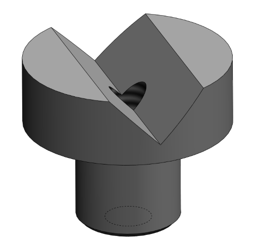
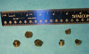
Flat Prismatic Components For Kinematics
In kinematic applications, plane flat surfaces have a higher load carrying capacity than cylindrical or spherical ones. Flat surfaces with very fine surface texture are quite slippery, so they provide excellent alignment of the mating spheres. Producing high quality flat planes on prismatic devices requires a unique approach. Lapping the inside flat faces of a Vee Block or even worse the inside faces of a Trihedral Cup is not at all a practical task.
An approach that can produce the highest quality internal prismatic devices is the split design. Instead of constructing the device as a monolith, which is conventional wisdom, each facet of the prism is produced as a separate but symmetrical unit. A very high quality flat facet can be easily produced on the truncated surface of a cylindrical post. Rigidity is not lost by splitting the faces of the prism, because the cylindrical design provides a simple method for extremely rigid mounting. By machining a trench in the Kinematic Platform with an end mill that has the same radius as the cylindrical post itself, and gluing the assembly together under load, an extremely rigid assembly results.
The reason that this design can so far outstrip the rigidity of a monolithic component is not so obvious; but it is due to the inherent weakness in the joint connecting the monolith to the Kinematic Platform. For light loads, there is seldom any reason to use this more complicated flat facet design, when three spheres will form an excellent trihedral cup and two cylinders a fine Vee Block.
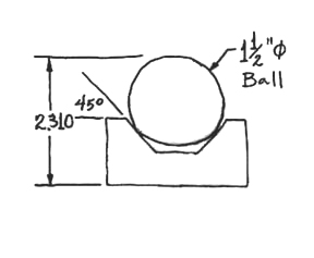
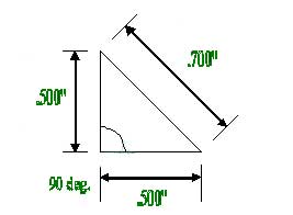
A universal component that will fill a broad array of high load kinematic applications is a three quarter inch (19mm) diameter cylindrical post that is truncated at a 45 degree angle. This one component will function well with any ball size from one half inch (13mm) to over one inch (25.4mm). Better repeatability can be achieved by using a steeper angle but this will reduce the load carrying capacity.
These components can be produced for surface mounting by drilling and threading a hole in the flat base but in doing so much of the systems rigidity is lost. Because the relative cost of raw material is rather small, in relation to the overall cost of this component, tungsten carbide with its tremendous stiffness or Young's Modulus of Elasticity of 98,000,000 P.S.I. and high hardness of 91-HRA has been chosen as the standard material.
There is wide latitude of design options of both size and materials to cope with different loads, corrosive environments, temperature, as well as magnetic and electrical qualities. We will custom build just about any design to fill specific customer needs. The average price for a steel Prismatic Post is $45.00 ea.
Split Kinematics Without Abbé Offset Problems
How can four points be good Kinematics? For anyone who has tried to level a four-legged table their answer will probably be that it is impossible. The subtle principals behind the excellent performance of all kinematic couplings is the fundamental nature of spherical geometry and the self aligning nature of three contacts.
| Downloads | ||
|---|---|---|
| Solidworks | IGES | |
The simple fact is that every point on the periphery of a sphere has a common point axis. When balanced vector forces are applied to the surface of a sphere, the resultant of those forces manifests itself at the center.
When working with Kinematic couplings, you can toy with the surfaces that transfer the forces to the spheres almost at will; but if you expect predictable results, you dare not mess with the spheres themselves.The question then is, "how can we split the Kinematic system to steady a clumsy platform that is unstable?" If we believe that we can cheat almost at will with the force drivers, then we can take a simple element like a Vee Block or Parallel Cylinders, saw it down the middle, and spread the pieces. The problem, of course, is how can we do our thing on the spherical part of the coupling? Using two small spheres or cutting a sphere in half and spreading the parts out until they contact the separated walls of the Vee Block will leave us with alignment and positioning problems that would make you wish that you had opted for a plain prismatic design in the first place. The answer is to simply go back to the principles.
If the target surfaces of the split Vee Block are four inches apart, then we need a single sphere that will be tangent to these surfaces. But a four-inch or larger ball is far too big, too heavy and too expensive to be practical. From the discussion so far, a viable solution is deducible. All that is needed is two small spherical segments with the proper spherical radius rigidly mounted tangent to the faces of the split Vee Block.
The method of attachment will dictate the actual design perimeters of these spherical segments with the only constraints being their radius of curvature and that their tangent contacts bisect at the appropriate spherical radius. This is presented for basic design information of how to do it as the component, for each design must be custom manufactured.
Our large array of spherical lapping tools assures fast delivery of these custom components. Extra threaded mounting holes may be machined into the split vee blocks for an additional charge.
Cheating
I love to cheat the system a little, when I can get away with it! When you can break the laws of physics, or at least give them a good bend and walk way scott-free, it is a warm sunny day. When coupling two bodies together, with a high degree of accuracy, three points of contact, or the “tripod rule” is a marvel, but in a rectilinear world, three equilateral points of contact, don’t match the rectangular parts.
The problem gets even worse when the aspect ratio of the mounting platform, doesn’t lend itself to an equilateral three point, coupling design. By using a pseudo Maxwell kinematic system, that basically consists of two standard Vee Blocks and one split vee block with four mating spheres, you get a perfectly functional kinematic coupling, that has the much more stable, four legs of support.
We produce a broad line of standard off the shelf Vee Blocks and Vee Block like products. We also produce several unique, off the shelf, split vee blocks. The technical aspects of using the split kinematic technique have been published by Dr. Alex Slocum of M.I.T. as well as by our company (See the list of technical papers on our website).
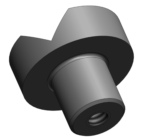
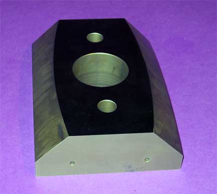
The Canoe Sphere
The original canoe sphere was a very robust, two-inch (50.8mm) diameter device that was developed to cope with very large, very heavy kinematic applications. This large, two-inch diameter canoe sphere uses a huge, forty-inch (one meter) spherical diameter and exactly matches our standard VB-2000 vee blocks. This combination will safely support 15,000 pounds (6804kg). This is 5000 pounds (2268kg) per couple.
As soon as the original CS-2000 became a well-accepted product, we started receiving requests for devices with a heavy load carrying capacity, but with a much smaller foot print. In answer to these requests we developed our smaller CS-1125 canoe sphere. These devices are compatible with our VB-750 series vee blocks.
This much smaller device uses the same, huge, one meter (40 inch) diameter spherical surfaces, but the diameter of the part is only, one inch, one hundred and twenty-five thousandths of an inch(28.575mm). This product has become a well-accepted addition to our kinematic product line. As soon as this new, much smaller product, was in use, our customers in the lithography industry started clamoring for an even smaller version. Going even smaller poses some difficult design issues.
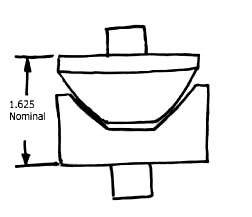
In order to grind the huge forty inch (one meter) diameter spherical surfaces to the microinch accuracy required for kinematic applications, we had to build a 40,000 pound monster grinder to produce these parts. The ideal diameter of the subminiature version of the canoe sphere, was determined to be three quarters of an inch (19mm). In order to appreciate the new problem created by the much smaller components it will require an understanding of the “Meniscus”.
The meniscus is the height of the high point on the “section” of a sphere, to the low point. The problem that occurs when very small sections of a very large spherical diameters are used is that the peak of the spherical contact to the lowest isn’t enough to cope with small misalignment. In the case of a three-quarter inch (19mm) diameter disk, it would have less than two thousandths of an inch (.0508mm).
In order to cope with this situation we had to reduce the diameter of the sphere from one meter (40 inches) to one half of a meter (20 inches). This new device (part number CS-750) is built to cope with loads in the seven hundred pound (317.515kg) range.
Part Number 2000-CS, in Stock and Ready for Immediate Delivery
| Downloads | ||
|---|---|---|
| Solidworks | IGES | |
Building giant heavy structures that must be kinematically supported presents some major problems. The required load carrying capacity of the spherical elements of the kinematic coupling is the major limiting factor. Directly related to this is the very high load placed on the mating surfaces that are in contact with the spherical elements.
The use of large diameter spheres or large diameter spheres made of very stiff materials is an excellent approach; but this can only be taken so far, and these structures become so bulky that they aren't at all practical. The not so simple solution to these opposing problems is to construct kinematic elements that consist of segments or slices of a very large spherical diameter or ellipses.
By building these spherical devices as compact monoliths that consist of two sections of a large spherical diameter, which are inset from the normal centerline, but with a common axis of symmetry, the job can be done. An ultra fine grain, high chrome, high carbon, stainless steel that is hardened to 58 HRC minimum, is the material of choice, because of its high quality and for economic reasons.
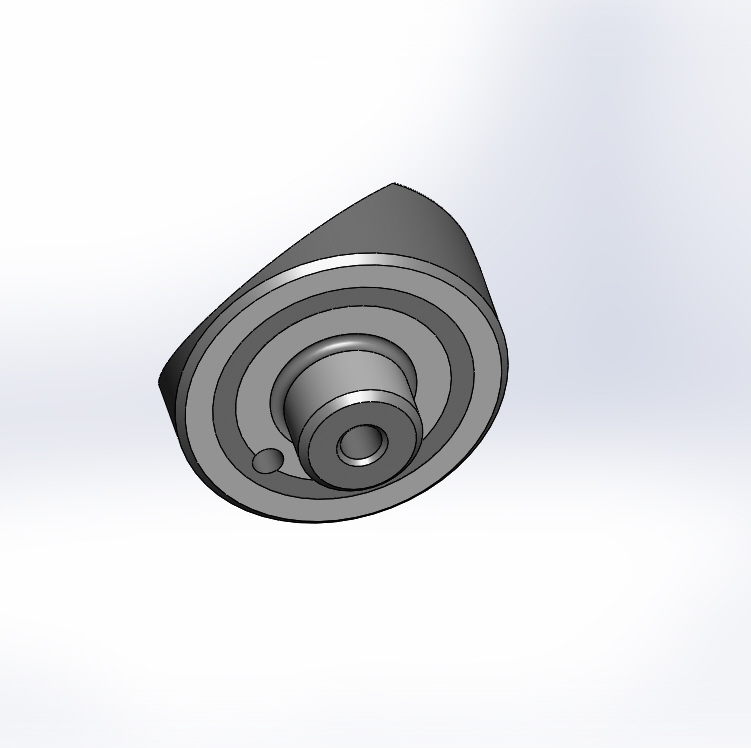
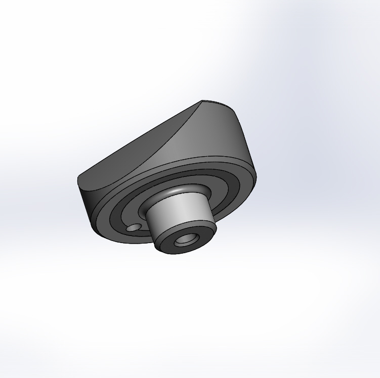
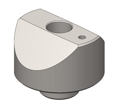
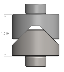
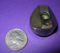
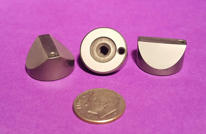
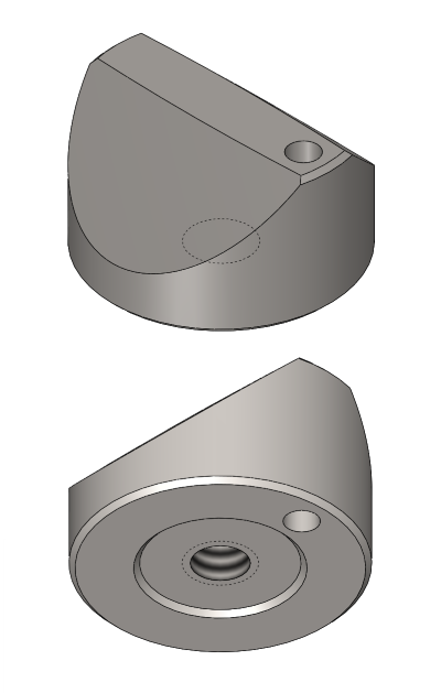
Cemented Tungsten Carbide ( TC ) would provide far superior results, but at a much greater expense and longer lead-time. The "Canoe Sphere" ( part number 2000-CS ) is a cylindrical post-mounted device that is now a catalog item. Like many of our other Kinematic designs, the center hole of the cylindrical post is threaded for M10 X 1.5 for clamping from the rear. As an alternative clamping method, it also has a 5/16-inch (0.3125", 8 mm) counterbored hole through the length of the post, so that it can be held in place with a 5/16-inch (0.3125", 8 mm) diameter socket head cap screw from the front.
There is a 3/16" diameter ( 0.1875", 4.76 mm ) dowel-pin hole off to one side, but exactly on the centerline of the post. Using this dowel-pin hole as a reference datum for interchangeability, the Canoe Sphere can be precisely located in a system. The large spherical diameters are precision ground using this dowel-pin hole as a datum. The surface texture generated by the spherical grinding operation has a lay that is parallel to the axis of the cylindrical post so it is in line with the engaging surfaces, to give it superior repeatability.
The Canoe Sphere is built on a two-inch diameter circle. The three-quarter inch ( 0.75", 19 mm ) diameter, one half inch ( 0.5", 12.7 mm ) long post, is precision ground to a tolerace of plus 0.0000 inches or minus 0.0005 inches (.013 mm). The adjacent flange is precision ground flat and square to the diameter of the post.
The spherical diameters ground on the segments of the Canoe Sphere are 39.4 inches, which is one meter. >When used in conjunction with our large 90-degree vee block (our part number 2000-VB-CPM), each canoe sphere ( Part No.: CS-2000 ) will safely support 5000 pounds.
When using the Canoe Sphere and Vee block, there are no loose pieces. This is of special importance in airborne applications. Use a 5/16" ( 8 mm ) hexagon socket head cap screw for top mounting. For bottom mounting, use M10 X 1.5 hexagon socket head cap screws.
The Miniature Canoe Sphere
Part Number: CS-1125-CPM
| Downloads | ||
|---|---|---|
| Solidworks | IGES | |
Until the advent of the Canoe Sphere, kinematic systems had a very low load carrying capacity for their physical size. It took huge spheres and large matching components to safely support even a few hundred pounds load. By using small segments of very large spheres ( one meter - 40 inches ), it is possible to very accurately locate huge loads of many thousands of pounds.
The original product was the rugged CS-2000-CPM which has a two inch ( 2.0", 50.8 mm ) diameter circular foot print. This has been a very popular product, but it is quite bulky for use in close situations. We have now introduced the much more petite version of the canoe sphere, with a circular footprint of only one and one eight inch ( 1 1/8", 1.125", 28.6 mm ) diameter. This is our part number CS-1125-CPM. This canoe sphere will mate with our off the shelf vee block, which is our part number VB-75-CPM or VB-75-SM.
The Combination Canoe Sphere and Vee Block — Part Number VB-CS-2000
There are about twenty interrelated dimensions that influence the perfect function of the canoe sphere and vee block combination. This includes the internal angles of the vee block faces the same applies to the external variation of the external canoe spheres and their angular relationship to each other and the flat flange area, the dimensional variability of the Vee Block faces and their locations, any variability in the somewhat complex relationships of the Vee block and canoe sphere faces to the axis of the cylindrical post, and the flatness of the vee block faces and the size and sphericity the canoe sphere faces.
For these reasons we are offering matched-sets of canoe sphere and vee block combinations that are perfectly matched by selection. Although the canoe spheres and vee blocks are fungible in that any two parts will work, together, these matched sets are perfect matches. There is no premium charged for this extra service and each matched set are laser engraved with identical serial numbers.
We have designed spherical lapping machines that will further improve the already excellent quality of geometry and surface quality of the canoe sphere faces. If anyone out there needs this improved quality, please let us know and we will move ahead with this project. There just isn’t time to complete all of the projects that we have conceived.
The weakest member of the canoe sphere and vee block combination, is by far the vee block. In a proof test to destruction, the Vee block failed at 4000 pounds (1820 kg). At the end of this test, the canoe sphere showed absolutely no sign of permanent deformation. The canoe sphere should theoretically function to over 5000 pounds. (2273 kg).
See here for the Vee Block prices.
The Subminiature Canoe Sphere - .750" Canoe Sphere
Part#: CS-750-SM
We have developed a 3/4" diameter Canoe Sphere (19.05mm) for even smaller applications. These have a spherical radius ground and lapped into its contact faces of approximately 10" (.25 m). We have built a unique, single-purpose machine that precision-grinds the desired radius, and only that radius, into this part. This part features the same ultra-fine-grain, high-chrome, high-carbon, 440C stainless steel hardened to 58 HRC minimum as our other Canoe-Spheres.
It uses a surface-mounted design with a blind hole on the bottom with a 10-24 thread, clamped from the rear, with a single .09375" alignment pin hole to the side. The bottom is also ground and lapped flat. It can be easily paired with our Surface-Mounted Veeblock (part # VB-75-SM), or our Mid-Size Post-Mounted Veeblock (part # VB-375-CPM).
This part (#CS-750-SM) is available for an investment of $145.50.
| Downloads | ||
|---|---|---|
| Solidworks | IGES | |
Monster Canoe Sphere
Huge spherical kinematic components, very large canoe spheres
The Monster Canoe Sphere is our part # MCS5000. It is a very robust size at 5.908” long (150.0632mm), 4.26” wide (108.204mm) and 1.535” thick (38.989mm). This device uses conventional canoe sphere design with two, full one-meter diameter (approximately 40”) spherical contact surfaces. These large spherical surfaces are what provide the huge load carrying capacity of the Canoe Spheres.
Each one of these devices is capable of conservatively supporting a load of 5000 lbs. (2267.962 kilograms). The Monster Canoe Sphere is manufactured from martensitic stainless steel that is through hardened to 58 HRC. In addition to its good hardness and corrosive resistance, this material has a very fine grain structure which enhances the use of this material for kinematic couplings.
The lay of the fine-ground spherical surfaces on the canoe spheres is almost perpendicular to the contact axis, instead of parallel for convenient grinding. This feature adds dramatically to repeatability of these devices. To start, a small-diameter hole is put all the way through the geometric center of the thickest dimension of the Monster Canoe Sphere. This hole provides a good starting point, enabling us to wire E.D.M. a large-diameter very precise hole, or other desirable geometric configuration. The monster Canoe Sphere weighs 8 pounds (3.62874 kilograms). There is a single1.725" (43.81 mm) through hole in the center, and two dowel pin holes approximately .525" (13.33 mm), that provide very positive location of the Monster Canoe Sphere on the platform.
Custom Canoe Sphere
Special custom-made versions of the Canoe Spheres can be produced for a reasonable cost in a matter of weeks. The basic shape of custom produced canoe spheres can be made any desired geometry, and the spacing between the spherical segments can be any practical dimension.
The choice of materials for Canoe Spheres is quite limited, because of the very high stresses that are involved with a sphere in contact with a flat. The standard material for manufacturing Canoe Spheres is a Martensitic stainless steel. This very fine grain material is hardened to 58 HRC. This material has a very high tensile strength of 285,000 PSI. The desirable parameters are high Young’s modulus, fine grain, good hardness, high tensile strength and some corrosive resistance.
The machine used to grind the 40 inch (one meter) diameter spherical surfaces on the Canoe Sphere is a one-of-a-kind, custom-built machine that can not generate any other radius. If you have an application that requires ultra-precise performance that is beyond our ground parts, we have designed a custom lapping machine that will improve the sphericity and the surface texture of the spherical surfaces of the Canoe Sphere. If you have an important application that requires more accurate location of heavy loads, it will require three months for us to build this machine and lap the first parts for you. We are constantly trying to improve our products, but so far the present precision ground quality has been adequate for all customer needs.
Canoe-Sphere Meniscus Controversy
We get a constant barrage of skeptics, who consider the small meniscus (the distance from the peak to the low points) of the Canoe Spheres to be some kind of major problem or limitation. Let me put this situation in everyday terms. If we place a canoe sphere in the center of a veeblock we would have to rotate the teeny tiny canoe sphere (part # CS-75) approximately 5.4-degrees to go from the peak to the lowest part of the outer edges. Rotation limit for the #CS-1125 is approximately 4.0-degrees. And for CS-2000 the angle would be approximately 6.8-degrees.
The canoe sphere is usually used on larger, heavier applications. The longer the distance between the positioning of the canoe spheres, the less critical their relative physical positioning will be. This is both their spacing and their rotary orientation. As an example, given the roughly 5.4° rotation limit on our new Canoe (CS-750), for every twelve-inches of distance, there is 1.13” of ‘play’ in the alignment. With our CS-1125 canoe and its roughly 4° rotation-limit, .84” per foot of ‘play’ is tolerable. And with our large CS-2000 canoe and its roughly 6.8° rotation-limit, it will tolerate angular-misalignment of up to 1.43” per foot.
When using the Canoe Spheres we are always using the Maxwell kinematic system, with three Vee Blocks and three spheres. With this system you get the almost magical function of the tripod-effect. The three spheres on the ends of the legs of the tripod will automatically locate in a pattern that exactly matches the complex geometric location of all six faces of the three Veeblocks.
This automatic normalization of position dramatically reduces the necessary accuracy of positioning for component parts of the Kinematic coupling. Due to the tripod-effect, the required accuracy of the “X” and “Y” positions of the component parts almost doesn’t matter. These positions end up resolving themselves into the sine of their angular displacement error. Looking at it from another standpoint, the consequence of the “X” and “Y” errors would resolve themselves as their very small vector resultant.
The very good surface finish and the fine grain structure of the hard martensitic stainless steel that we use in the construction of both the Canoe Spheres and the Veeblock, provide a very slippery slope that guarantees the very accurate repeatability of the entire platform in all six degrees of freedom.
An easier way to visualize the function of the Canoe Spheres is to imagine it as a complete ball. If it were a complete ball we could literally rotate it a full 360 degrees. With the Canoe Sphere this rotation is somewhat limited but it is still very substantial.
Vee Block Pricing
| Part # | Description | Price | Purchase |
|---|---|---|---|
| CS-1125-CPM | CANOE SPHERE, MINIATURE, 1.125" | $160.00 | |
| VB-5 | ROUGH ALUMINUM VEE BLOCK CASTING | $129.00 | |
| VB-187-CPM | VEE BLOCK, 0.1875" ( 3/16" ), CYLINDRICAL POST MOUNTED | $50.60 | |
| VB-375-CPM | VEE BLOCK, 0.375" ( 3/8") CYLINDRICAL POST MOUNTED | $50.60 | |
| VB-375-SM | VEE BLOCK, 0.375" ( 3/8") SURFACE MOUNTED | $50.60 | |
| VB-75-CPM | VEE BLOCK, 0.750" ( 3/4" ), CYLINDRICAL POST MOUNTED | $50.60 | |
| VB-75-SM | VEE BLOCK, 0.750" ( 3/4" ), SURFACE MOUNTED | $50.60 | |
| VB-2000-CPM | VEE BLOCK, 2" CYLINDRICAL POST MOUNTED | $173.00 | |
| VB-2000-SM | VEE BLOCK, 2" SURFACE MOUNTED | $173.00 | |
| SP-VB-45 | VEE BLOCK, 45 DEGREES, SPLIT | $24.23 | |
| SP-VB-XTH | VEE BLOCK, SPLIT, EXTRA THREADED HOLE | $19.80 | |
| SP-VB-XTH-SET | VEE BLOCK, SPLIT, THREADED HOLE SETUP CHARGE | $38.50 | |
How to Align Canoe-Spheres on Veeblocks
A common question is how to precisely align canoespheres with veeblocks.
It does not matter too much that the couplings be in perfect position as long as they are close to the ideal; they will easily tolerate a few degrees of misalignment before you run into any issues with the contact surfaces bottoming out and disrupting the coupling. If you are just making a one-off device, the easiest way to align the couplings is to use a little bit of Prussian Blue on the canoes--be sure the layer applied is very thin, and join the coupling, then separate them and verify that the contact points of the canoes on the vees, as shown by the dye transfer, are not hitting the edge of the veeblocks but contact somewhere in the middle of the veeblock faces.
You should see a dot of pigment on the contact-face of the vees, showing the point of contact between them, in a place on the vees that is not touching an edge of the vee. If they are hitting the edge, the vee or canoe can be repositioned by hand and re-checked in the same way. If you want to produce a more perfect or precise alignment than that, or if you want to align them in a volume-production environment, it can be done rapidly, without rechecking by hand, if you build a simple alignment-jig which allows you to put the jig in place, and the alignment of the canoes is automatically corrected by the jig itself.
The jig must be made specific to your setup and spacing, but the principle is the same. Two slightly-splayed (non-parallel) precision-cylinders are caused to be brought down on each canoe, forcing them to align with the proper Y-direction. Here is an example of how a jig like this could be made:
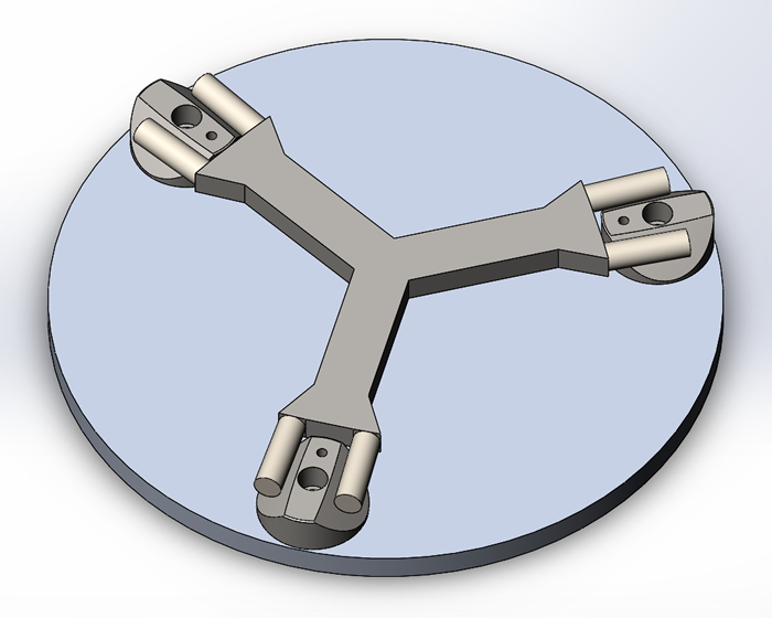
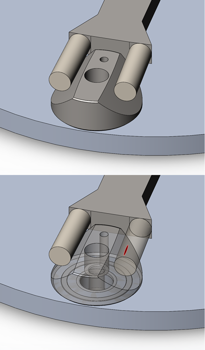
By contacting off-center, near the edge of the canoe, the loosened canoe is forced to self-align as the jig is brought down on it. It can then be tightened in place, leaving the canoes very close to the ideal alignment. The splay-angle as shown is subtle, but each cylinder is two-degrees off parallel, 4° total, using .5" precision-ground and polished cylinders, spaced apart by .875" (1.375" from center of the cylinder to center, on the narrow side), held on a simple piece of steel by some means.
Again, for a one-off design, building a jig is probably more trouble than it's worth, using the Prussian-pigment transfer technique to check mating surfaces is more than sufficient. But for those looking to go into volume production, a jig like this can turn a laborious alignment process into a straightforward one. And in cases where use of the alignment-hole is insufficient, not expected to be accurate enough, or undesirable to use, a jig like this can offer excellent alignment quality. It will also produce a more parallel coupling.
A similar principle can be used to perfectly align the veeblocks themselves, using a single Y-shape cylinder that contacts all three veeblocks in a similar manner, causing them to self-align.
In the past, slight angular-misalignment of the canoes and veeblocks would give a Z-resultant, affecting the parallelness of the kinematic platform. But the ability to control the Z-axis precisely using the Flexasphere and Flexacanoe has made this kind of control of alignment by perfectly aligning the kinematic components much less critical than it once was, allowing precision-platform control.