Bal-tec™ Home Flexural Encyclopedia
Flexural Encyclopedia
Introduction
Researchers who dedicate their lives to a narrow field of science, often miss the reality that most practitioners are only seeking a satisfactory solution for a single problem. These researchers have no desire to become overall experts in this or that esoteric discipline.
This encyclopedic approach is an effort to disseminate requisite flexural information where needed.
The Accuracy of Flexures
Hitting the bull’s-eye of a target is accuracy and hitting the same place on the target is repeatability. We can say that flexural assemblies are extremely repeatable, but they are not always that accurate. What this means is that the movement of a flexural assembly may have to be measured and documented, then this map is used to compensate for the lack of accuracy in the actual application.
The Assembled Flexure
An assembled flexural system, consists of several individual parts including the bodies, the leaf flexures and the clamping plates, which are all rigidly connected together to form the functional device.
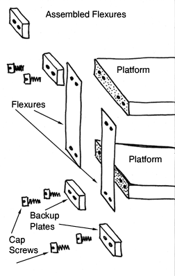
The one serious limitation to the assembled flexural system was the low efficiency of coupling the leaf flexures to the bodies when mechanically machined leaf flexures were being used. Poor connection of the flexures to the bodies would cause huge losses in the transfer of energy by the system with the ensuing inaccuracy.
The contact surfaces where the flexures are mounted on the bodies of the assembly should be machined as flat as possible with an excellent surface texture. The contact surface of the clamping plates should be flat lapped to provide as much clamping area as possible. This statement is in direct contrast with many if not most instructions for the design of clamping plates. The prevailing wisdom was to machine reliefs in the center of the clamping plates to concentrate the clamping stressed, adjacent to the bending or hinge line of the leaf. Everything about this practice is wrong. When the compressive force of the cap screws is applied to the “U” shaped clamping plate, the center will bend down; even further reducing the clamping area of this design. The extremely high stress concentrations immediately adjacent to the hinge line will accelerate fatigue failure.
In all fairness, this design for the clamping plate was developed before wide spread use of Electrical Discharge Machining ( EDM ), eliminated the bending and burs created by mechanical drilling and machining of leaf flexures.
The final machining of the leaf flexures themselves should be accomplished by EDM only. Using the EDM process there is no physical contact between the cutting tool and the part being machined. This process only uses sparks of electrical energy that burn millions of tiny craters, leaving the desired contour of the finished part remaining. There is no mechanical bending of the part and there are no resulting burs.
By using the best design and manufacturing practices, very highly efficient flexural assemblies can now be produced. Assembled flexural systems are several orders of magnitude less expensive than the alternative, monolithic systems, and the necessary planning and construction takes an hour instead of a day. The best computer simulation of a flexural system can be off 30 to 50%. With assembled flexures you can just substitute thicker or thinner flexures to correct a deficiency, and you are immediately in business. When there is a deficiency in a monolithic system, you go back to square one and start all over again. A wide variety of leaf flexures in various widths lengths and thicknesses are commercially available. A variety of clamping plates are commercially available. (See “Leaf Flexures” and “Clamping Plates”),
The Backup Plate
See The Clamping Plate
A Bellows Flexure
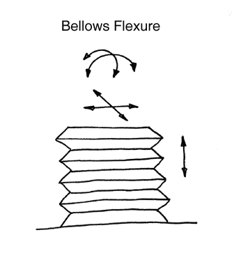
A bellows flexure is one of the more complex forms of flexure. The design of the Bellows can be broken down into two basic configurations.
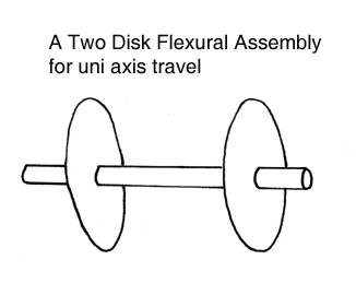
What we will call the horizontal or disk bellows, is very widely used as a true flexure. The disk bellows flexure consists of a disk of rather thin metal, with a consistent pattern of convolute undulations, formed in the flat face. This configuration is very stiff in the “Y” axis, which is forward and back movement, in the “X” axis which is side to side movement as well as in the “Yaw” axis, which is rotation around the “Z” or up and down axis.
With this flexure, the “Z” or up and down axis, is free to move. It is also free to “Roll” around the “X” axis and to pitch around the “Y” axis. By rigidly mounting one of the disk bellows flexures at each end of a widely spaced assembly, all of the movements in pitch and roll will be eliminated, leaving a uniaxial “Z” axis movement. The better known vertical bellows is a cylindrical tube with a consistent pattern of convolute undulations in the cylindrical diameter. This bellows exhibits the same degrees of freedom and the same constraint pattern as the horizontal disk flexure, but it can have a very considerable travel of the “Z” axis.
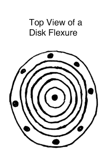
If the length of the vertical bellows is made quite long, it will become loosy in the “X” and “Y” axii. (See loosy in “The Kinematic Encyclopedia”). Instead of simple radii, the convolutes of the bellows can be formed into complex contours that promote longer more linear “Z” axis motion.
The Blade Flexure
See Leaf Flexure)
The Bowed Flexure
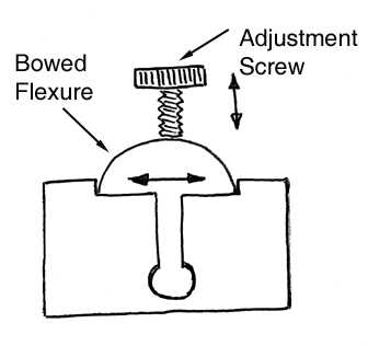
The bowed flexure is usually used as a fine motion adjusting device. By pressing down in the center of a bowed flexure, the end length increases. This increase in length is in direct proportion to the rise of the bow to the overall length. A five to one reduction ratio is a reasonable design criterion, which can be achieved, without pushing the tendency of this design to “Tin Can”. (See “Tin Canning”). The bowed flexure can be a single bent beam or it can be a 360° closed structure, usually of an elliptical form. The extremely versatile capabilities of the computer controlled wire, EDM, centers opens wide design vistas for the use of the bowed flexure. (See “Electrical Discharge Machines”).
Buckling
Buckling is the structural Instability that occurs in the thin areas of a structure when it is placed under a certain compressive stress or load. Elastic Buckling will recover when the compressive load is lowered or removed. Plastic Buckling is a permanent catastrophic or destructive failure and there will be little or no recovery.
This condition is often referred to as columnar buckling. (See Euler equations)
The Cantilever Rotary Flexure
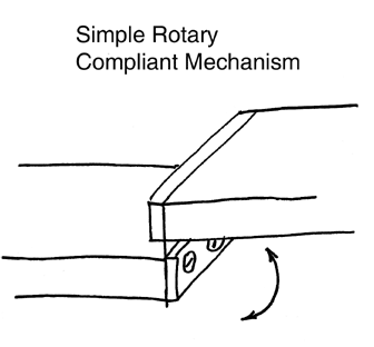
A cantilever is a flexural beam rigidly supported at one end only. All flexures are fundamentally hinges. The simplest form of flexural hinge is the cantilever flexure. A cantilever flexure is a single leaf or notched flexure rigidly clamped between the two sections of a mechanism with one fixed and one free to rotate. It will give good rotary deflection, but it is sensitive to parasitic or off axis movements.
The Cantilever flexure, used as a rotating hinge, should be as long as possible and the width or height should be as short as practical. The larger the aspect ratio of the cantilever rotary flexure, the less sensitive it will be to parasitic and or off axis movements.
Leaf flexures and clamping plates, forming cantilever flexures, are commercially available in a wide variety of lengths, widths, and thicknesses. (See “Leaf Flexures”) (See “Clamping Plates”).
The Clamping Bar
See The “Clamping Plate”)
The Clamping Plate
The clamping plate is used to rigidly attach the ends of leaf flexures to the mating parts of a flexural assembly.
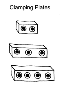
The main weakness of assembled flexures is the joint between the flexure itself and the bodies of the assembly. To make this coupling as rigid as possible, the clamping plate should be of very rugged construction. The goal of the assembled flexure is to achieve as nearly 100% contact between the flexures and the bodies of the flexural assembly as possible. To achieve this goal, the surface of the clamping plate in contact with the flexure should be flat lapped. This statement is in direct contrast to most design advice being given currently. It is usually recommended that the clamping plate be relieved in the center. When the clamping screws are tightened using this design, the “U” shaped clamping plate bends at least slightly, leaving two very narrow lines of contact to clamp the leaf flexure in place. Generating these very high localized, compressive stresses is not a good way to secure the leaf flexure, and it will ultimately reduce the fatigue life of the system.
The surfaces of the bodies of the flexural assembly that mate with the flexure itself, should be carefully machined as flat as possible. The mounting holes in the flexures and the ends of the flexure, should be Electrical Discharge Machined to prevent any physical distortion or burrs, of the flexure, which will be caused by conventional mechanical drilling or punching. The clamping screws should be as large as possible and as many screws as possible should be used.
To prevent fatigue cracking, of the leaf flexure, due to stress risers, generated at the junction of the flexure and the body of the assembly, there should be a substantial tangent radius on both the body of the assembly and the adjacent edge of the clamping plate. A variety of clamping plates are commercially available for flexural applications. (See “Leaf Flexure”). (The term “Clamping Plate” has also been used in the literature to describe stiffening plates). (See “Stiffening Plate”).
Columnar Buckling
See “Buckling”
A Compliant Structure
Compliance is to move with a force, or not to resist, a force. The term Compliance is often used to describe the free movement of an entire system and the term flexure is used to describe the individual sections of the structure that move.
Compound Linear Flexure
The elevation of the moving platform of a standard four bar flexural system will drop slightly when the platform is actuated. To correct for this drop, a second platform, with the same length flexures, is suspended under the first platform. When this second platform is actuated it raises up the same amount that the first platform drops down so the net result is perfectly linear motion.
Note that for the second platform to provide truly linear motion, it must be actuated at the center distance between the two platforms, by a decoupling mechanism such as a wobble pin, a dual axis notched flexure or a toroidal flexure. (See “Wobble Pin”)(See “Four Bar Flexure”) (See “Leaf Flexure”) (See “Clamping Plate”) (See “Dual Axis Notched Flexure”) (See “Toroidal Flexure”).
The Crescent Blade Flexure
The Crescent Blade flexure, is a linear translation device. A single Crescent Blade flexure is free to move in the “Z” axis. It is free to rotate in Pitch” and “roll”. It is very stiff in the “X: axis, in the “Y” axis and in “Yaw”.
A crescent blade flexure must have at least three blades or leafs to stabilize the translation motion. As the “Z” axis translation progresses there will be a small Yaw motion imparted to the travel due to the shortening of the flexures. Two sets of these crescent flexures, with a substantial separation between then, will eliminate all “pitch” and “roll” leaving pure “Z” axis translation. The significant design feature of the crescent flexure is that there is no obstruction down through the center, so that optical or mechanical apparatus can be located there. Many variations on this basic design have been built.
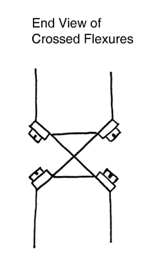
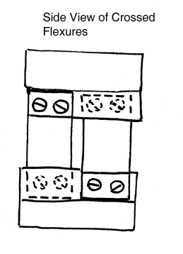
Crossed Leaf Rotary Flexure
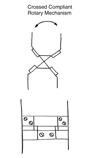
The crossed leaf rotary flexural system, is always an amazement to first time observers. It isn’t just the velvet smooth rotary motion it imparts, as much as it is the rock solid resistance, to any attempt to twist it even the slightest amount, off its rotary axis. I have seen first time observers turn red in the face, with their frustration at futilely trying to twist, what looks like a very flimsy set of flexures, even the slightest amount off the rotary axis.
The crossed leaf rotary flexure is simply two or more cantilever flexures mounted at right angles to each other.
The crossed leaf rotary flexure design is somewhat more complex than the pup tent flexure, but it is orders of magnitude better, in off axis stiffness and resistance to parasitic motion.
A wide variety of leaf flexures are commercially available in different widths, lengths, and thickness. (See “Leaf Flexures”) (See “Clamping Plates”) (See “Pup Tent”).
The Cruciform Flexure
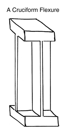
The Cruciform is a rotary flexure. The flexures have a cross section in the form of an “X”. The head, the base and the cross shaped flexures, of this device, are a monolithic structure. This form provides a very compact structure with a high buckling load capacity. The Cruciform flexure has a rotational freedom around the “Z” axis, which is “Yaw”. All of the other five degrees of freedom are very rigid, in this design. More leafs can be added to the basic cruciform design which will add to the load carrying capacity. (See “Paddle Wheel” which is a similar design).
Damping
Flexural systems that are not heavily preloaded will be very sensitive to environmentally induced mechanical vibration. In some cases, air or oil filled dashpots are used to provide damping of the flexural system. This type of damping can be effective, but it will dramatically reduce the frequency response of the flexural assembly.
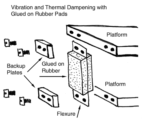
An effective technique that will dramatically reduce the flexural assembly’s sensitivity to vibration is to apply a layer of high hysteresis rubber to the surfaces of the flexures themselves. This can be done in two ways. A layer or layers of a self curing rubbery compound can be applied directly to the exposed surfaces of the flexures themselves. The second and much better method is to glue a layer of the rubbery material directly to the surfaces of the flexures. This second method has a distinct advantage in that a thin layer of metal can be pre-attached to the rubber layer, which turns this mechanism into a much more effective shear strip damping system. This technique of damping will have only a small or no effect at all on the frequency response of the flexural assembly.
These same methods will provide excellent thermal damping. The very large area to thickness ratio of leaf flexures makes them subject to instantaneous dimensional perturbations with changes in temperature. The thermal insulating properties of the rubber coating will dramatically reduce the flexure's response to temperature changes.
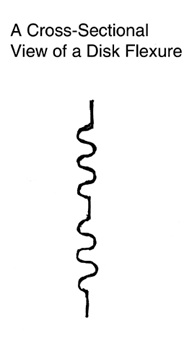
The Diaphragm Flexure
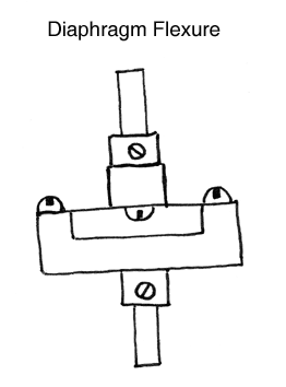
The diaphragm flexure is used mainly as a rotary coupling device. The diaphragm flexure consists of a thin, round flexible disk of metal, with a mounting hole in the center, and a series of holes near the periphery to attach it.
This configuration is very stiff in the “X” axis, which is the side to side movement, in the “Y” axis, which is the forward and back movement, as well as in the “Yaw” axis, which is rotation around the “Z” or up and down axis. The Diaphragm flexure is flabby or loosy in the “Z” axis due to mild tin canning (See “Tin Canning”).
The main qualities of this flexure is its relative freedom of movement in the “Pitch”, which is rotation around the “Y” axis, or back and forth axis, and “Roll” which is a rotation around the “X” axis, that is the side to side and its extreme rigidity in the “Yaw” axis which is rotation around the “Z” axis, which is the up and down axis.
The full benefits of this simple inexpensive design can be gained by using two of these couplings in series with a separation between them.
It should be noted that an improvement in rotary coupling design can be achieved by using a disk bellows instead of the simple flat disk. (See “Bellows flexure”).
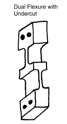
The Double Notched Flexure
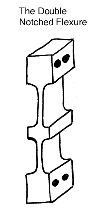
In order to concentrate the flexibility of a mechanism in local areas, those areas are thinned down considerably. The double notched flexure has two sets of parallel notches, in a single bar. The advantages of this more complex design over a simple leaf flexure, are that it provides two hinge lines, just as the simple leaf flexure does and it can be clamped to the mating mechanism with almost 100% efficiency, because there are no joints between the flexures and the body. In addition the cross section of the notches may be of a complex form, that will improve the linear travel of the system. These cross sections may be cylindrical, parabolized, elliptical hyperbolized or other complex shapes that can have some special effect on the linear travel of the transient section of the flexural system.
The ability to produce complex shaped cross sections with very thin flexure sections, has been made possible by the development of computer controlled Electrical Discharge Machines, but especially the Wire Electrical Discharge Machines. (See “Electrical Discharge Machines”).
The Dual Axis Notched Flexur
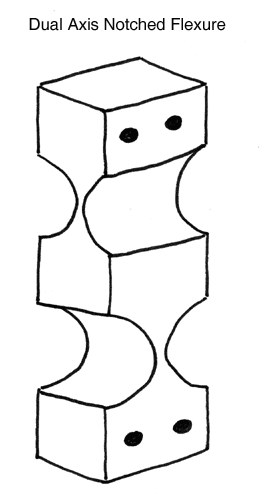
The Dual Axis notched flexure, is a popular design that is frequently used to isolate misalignment in “Pitch” and “Roll” from the input and or output of a mechanical system. This device will be somewhat loosy in the “Yaw” axis, depending on the length and stiffness of the flexible sections. This loosy condition has led to the designation of this devise as having two and one half degrees of freedom. This device is very stiff in the “X” axis, in the “Y” axis, and in the “Z” axis.
It is the high stiffness in the “Z” axis and the good flexibility in the pitch and roll axii, that are the most desirable qualities of this device. This monolithic approach is often used for input and output of flexural devices instead of the three separate piece construction of the “Wobble Pin”. The function of the “Toroidal Flexure has very similar properties to those of the dual axis flexure so it should also be considered, when input and or output isolation is required. (See “Wobble Pin”) (See “Toroidal Flexure”).
Dual Toroidal Flexure
See “Toroidal Flexure”)
Electrical Discharge Machining
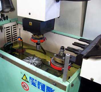
A basic knowledge of what E.D.M. is, how it works, and what it can do is an absolute must for today’s flexural designer. An E.D.M. uses sparks of electrical energy to “burn” or “erode” material away from the part being machined. The part being machined is separated from the electrode or tool of the E.D.M. machine by an electrolyte or dielectric fluid. The dielectric can be pumped between the electrode and the part or both the electrode and the part can be submerged in a tank of the dielectric. Pulses of electrical energy are applied between the electrode and the part. When the electrode is brought close enough to the part, sparks of this electrical energy, discharge between the gap. Each one of these sparks of electrical energy super heats a tiny spot on the surface of the part being machined. This burst of energy liquefies that tiny spot and the cooling action of the electrolyte expels a tiny ball of metal, leaving a spheroid in the surface. This action takes place thousands or even hundreds of thousands of times each second.
Compared with mechanical cutting processes E.D.Ming is a very slow process. Where drilling a hole takes only seconds on a turning or milling center, it takes multiple minutes on an E.D.M. machine, but an E.D.M. machine can cut the hardest materials and it can machine ultra precise parts without distortion or damage and these parts are burr free.
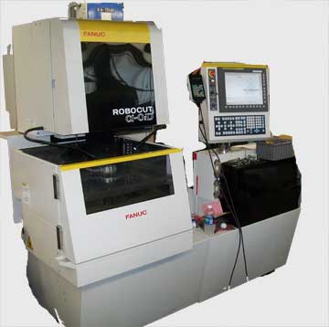
There are basically two forms of E.D.M. machine. There is the Die Sinking machine which closely resembles a vertical milling machine or Jig Borer, with a tank surrounding the work table. This type machine is used for drilling, shaping, and threading parts. The second type machine is the Wire E.D.M. machine. These machines are something like a vertical band saw, but with a wire instead of a flat blade, to do the cutting. These machines are fully computer controlled with complex multi axis machining capability. It is these machines that make possible the production of notched flexures with thin complex cross sections. It is this machine that has opened the door to the production of very complex monolithical flexural assemblies.
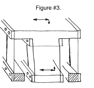
Four Bar Flexure
The four bar flexural assembly is probably the most widely used flexural design for simple linear flexures. It consists of a fixed and mobile platform coupled together by four leaf type, or four double notched flexures. The transient platform of the Four Bar flexure will dip slightly as it is actuated.
For the most accurate application the actuation and the output should be made on the centerline of the platforms at a position one half-way between the two platforms. To minimize parasitic and off axis rotation the actuation and the output of the Four Bar flexure, should be made through a decoupling mechanism such as the Wobble Pin or a multi axis flexure.
The characteristic dipping of the four bar flexure can be corrected by using the somewhat more complex compound flexure. (See “Compound Flexure”) (See “Leaf Flexures”) (See “Wobble Pin”) (See “Dual Axis Flexure”) (See “Toroidal Flexure”).
Frequency Response of a Flexural Mechanism
Flexures have a broad range of frequency response. This response ranges from zero to many kilohertz. The basic high end limitation is determined by the mass of the moving payload and any damping of the system. A loud speaker uses a bellows like flexure, to support the voice coil and the speaker diaphragm, in producing up to twenty Kilohertz of air pressure waves.
The Helical Flexure
The Helical Flexure is somewhat unique, as it produces a combination of precise rotary and linear motion simultaneously. This device can be an important addition to a precision engineer’s tool box. It has features that are in common with the paddle wheel.
In helical flexure design, the two platforms are separated by three or more flexures that are set at an angle, that is off the vertical axis, between the two platforms. When a force is applied between the two flexural platforms the transient platforms depicts a true helical path, made up of both a linear and a rotary element. This flexural bearing arrangement, is the universal design that is used on bowel type vibratory parts feeders.
A Leaf Flexure
A leaf flexure is a thin, flat, parallel plate, that is very flexible in comparison with the rest of the structure. These devices are used in assembled flexural systems. The drawback to using leaf flexures has been the large losses incurred, do to the poor coupling between the leaf flexures and the body of the flexural assembly. This poor coupling resulted from geometric distortions and burrs caused by mechanical machining. In past times the quality of these, usually thin, stiff structures was limited by the bending and burrs that were caused by the mechanical machining or metal stamping of the flexures. In modern machining practices, these thin parts are now machined by Electrical Discharge Machining, where there is no physical contact, of any kind, between the machine and the flexure. This process produces flexures of near perfect geometry, without any burrs or geometric distortions to hinder perfect coupling. (See “Electrical Discharge Machining” for a more detailed description of this process).
Leveraged Flexures
Flexural hinges or pivots are often used to multiply or to divide motion or force. The fact that this action is true multiplication or division and not just addition or subtraction, is very significant, in that large accurate changes in travel or force that can be made economically.
This multiplication or division is accomplished by using fundamental leverage with flexural bearings as the pivots or fulcrums. Large very accurate ratios can be achieved by coupling multiple sections together with a series of frictionless, hysteresis free flexural pivots.
The Monolithic Flexure
A monolithical flexural structure is very simply a complete flexural system machined in its entirety from a singe block of homogeneous material. Several of the advantages that are derived from this construction over an assembled flexural design are that it will have: one hundred percent efficiency in the coupling of the flexures to the body of the flexural system, much more compact structures can be built using the monolithic approach, and much more sophisticated contours of flexures can be employed that have unique flexural characteristics to improve the linearity of the flexural system. These cross sectional curves can include: cylinders, ellipses, parabolic curves, hyperbolic curves and simple tapered sections.
The use of modern computer controlled Wire Electrical Discharge Machine‘s, offers almost unlimited design versatility. (See “Electrical Discharge Machining” for a more detailed description of this process). The cost of building monolithic structures is very high. Mathematical calculations that predict the performance of a flexural system are not very accurate, so several iterations of the design will probably be required. Sophisticated computer aided design (C.A.D.) computer aided manufacturing (C.A.M.) programs must be written to direct the path of the wire’s cut. At the present time, ( circa 2009 ) the cost to operate a wire E.D.M. machine is about $100.00 per hour.
A Notch Flexure
In order to concentrate the flexibility of a mechanism in local areas, those areas are thinned down considerably. The geometry of the thinning is usually a pair of opposed cylindrical grooves, but ellipses, parabolas and hyperbolic forms can be used advantageously, to improve linearity. The notched flexure can be a stand alone device that is assembled into the overall flexural mechanism, or it can be machined as an integral part of a monolithic structure.
A notched flexure has the additional advantage over a simple leaf flexure, because it can be assembled with almost 100% efficiency. The construction of notched flexures has been greatly advanced by the modern development of computer controlled Electrical Discharge Machining, especially the development of Wire Electrical Discharge Machining. (See “Electrical Discharge Machining” for a more detailed description of this process). The cost of producing notched flexures is very high in comparison to assembled leaf flexures.
The Over and Under Flexure
The over and under flexure is one of the unusual, but powerful flexural designs. The moving platform has a right angle flexure at one end that points up, while the right angled flexure at the opposite end points down. When the platform travels, the flexures at each end of the platform foreshorten. This action pulls one end of the platform up, while the opposite end is pulled down. The interesting result is that the center of the platform maintains its central position, during travel. The longer the platform is in relation to the length of the flexures and the distance traveled the less average rotation will occur.
Parasitic movement
A parasitic movement is an unintended, undesirable, often off axis movement, of a flexural assembly. It is often, an off axis twisting movement, that imparts motion to the output of a flexural assembly, that did not exist in the original excitation. These parasitic motions can resolve as a first order and or, as a harmonic motion.
The insertion of a wobble pin or dual axis flexure between the excitation and the flexural assembly, will attenuate or eliminate this problem. By using a wobble pin, the actuating force will be applied on the central axis of the flexural assembly, so that near perfection in the energy transfer without parasitic movement is assured. (See “Wobble Pin”). Adding a toroidal or a dual axis flexure to the input and or output, is an alternative to the wobble pin that will also attenuate the tendency of parasitic movement. (See “Toroidal Flexure”) (See “Dual Axis Notched Flexure”).
The Paddle Wheel Flexure
The prattle wheel is a pure rotary flexure. One of its unique design features, is that its flexural elements are placed at right angles, to the more conventional rotary flexures, such as the cantilever, the pup tent, the crossed flexures and the wagon wheel. This characteristic may be an important design feature in some challenging situations. The slight dip, caused by the foreshortening of the flexures during rotation will be in line with the rotational axis of the system, not an off axis shift, which is characteristic of the more conventional rotary flexures.
The Paddle Wheel must have at least three flexures, but for structural reasons a multitude of paddles are often used. Using the multiple paddle (flexure) approach, high compressive loads can be accommodated without buckling. The Paddle Wheel can be constructed with washer shaped end plates so that there is a large center hole available to place an optical or electronic, payload on the rotary axis. (See “Cruciform Flexure” which is a similar design to the “Paddle Wheel”).
Preloading
You should not depend on the flexural elements themselves to provide the preloading or restoring force, for a flexural assembly. Dead Weight Preloading is an ideal approach. When the flexural systems is acting in a near vertical axis, this is a straight forward way of preloading or restoring the position of the flexure.
On systems that operate off the vertical axis, dead weight can still provide an ideal preload. The force of a vertically hung dead weight can be turned at an angle without any friction, stiction, backlash, or hysteresis by using a cable and a rotary crossed flexure arrangement. A more conventional approach, when less accuracy can be tolerated, would be to use a cable over a rotatable pulley.
A well placed coil or leaf spring is the next best form of preload for a flexural assembly. The dilemma of using a spring force of any kind is that the longer the travel of the flexural assembly the higher the preload becomes, while dead weight remains essentially constant. (See “Crossed Leaf Rotary Flexure”).
The Pup Tent Rotary Flexure
The pup tent rotary flexure is a slight improvement over the simple cantilever rotary flexure. It is much less prone to parasitic or off axis rotations than the cantilever. The pup tent remains a fairly simple, inexpensive, two flexure design. The “pup tent” flexure is very compact. The simplicity of the pup tent design makes it an inexpensive device to produce. (See “Cantilever Rotary Flexure”) (See “Crossed Leaf Rotary Flexure”) (See “Wagon Wheel Rotary Flexure”).
Range of Motion
The range of motion of flexural bearings is usually very limited. Simple mechanics, will dictate that the longer the flexures are, the farther it will travel. The longer a leaf flexure is the more susceptible it will be to parasitic or off axis bending.
A good method of increasing the travel of a flexure is by placing multiple flexural sub assemblies in series. A simple example of this technique, is the compound flexure arrangement. (See ”Compound Flexures”)(See “Parasitic Movement”).
A Reed Flexure
See “Leaf Flexure”
The Restoring Force
See “Preloading”
The Side Notched Flexure
The side notched flexure is generally found in miniature, low load applications, particularly in sensitive weighing applications. What it amounts to is that very small very sensitive flexures are extremely difficult to work with. It is difficult to accurately position them and it is difficult to attach such small devices, without damaging them.
By designing a rather robust base flexure, with rather large mounting surfaces, with large mounting holes and then necking it down from each side, very delicate, very sensitive flexures can be created, that are still easy to work with. The advent of computer controlled wire electrical discharge machining centers have opened the door to exciting design innovations that can be controlled at the parts per million levels. (See “Electrical Discharge Machining”).
The Split Diaphragm Flexure
The Split Diaphragm flexure is used when a considerable “Z” axis travel is required, while maintaining a high stiffness in all other degrees of freedom. A single Split Diaphragm flexure is free to move in the “Z” axis. It has limited freedom to rotate in both the pitch and in the roll axii. It is very stiff in “X” axis and in the “Y” axis. It is also very rigid to any rotation in the “Yaw” axis.
By mounting one of these split diaphragm flexures, at each end of a two diaphragm system, with a considerable distance between them, all freedom, in pitch and roll is removed from the system and only the single “Z” axis degree of freedom remains. Among all of the linear flexural systems this one is outstanding. This system performs much as a compound flexural system. As the tongue part of this flexure tends to move the centerline in one direction, the ring shaped part of this flexure pulls it back in the opposite direction, so the net off axis displacement is zero.
The Stiffening Plate
The stiffening plate is actually two plates, each one of which is several orders of magnitude thicker than the flexure. These two relatively thick plates are rigidly clamped in the center of the flexure, in a sandwich fashion. More often than not, a high strength epoxy glue is applied to both sides of the flexure to eliminate micro creep. This assembly is cured under a clamping force.
The stiffening plate will dramatically increase the buckling load capacity, of a flexure. The stiffening plate raises the resonate frequency, of the entire flexural assembly. The stiffening plate slows down the reaction time of the flexural system to thermionic change. This is due to the substantial increase in the thermal mass of this system.
The stiffening plate does all of this without substantially changing the physical properties of the flexural system. This is because each one of the linear flexures actually consists of two rotary joints, or hinges adjacent to the connection of the flexure to the body, this area adjacent to the connection is where all of the actual bending movement should take place. Other common terms for the stiffening plate is the clamping plate and the tuning plate.
Thermal Sensitivity
Typical flexures are subject to almost instantaneous reaction to temperature changes. Typically the area of the flexure is very large and the cross-section is very small so temperature changes cause dimensional changes very quickly. This large and rapid change is limited to the long axis of the flexure which is not usually as critical for the function of the system.
To slow down the effects of temperature change, on the flexural assembly, the flexures can be coated with a layer of high hysteresis rubber or a layer of high hysteresis rubber can be glued on to the flexure. Applying a high hysteresis rubber coating has the added effect of providing mechanical damping, that attenuates deleterious vibration, which will enhance the overall performance of the flexural assembly. Adding stiffening plates to the flexural assembly will dramatically slow down the thermal sensitivity due to the dramatic increase in thermal mass. Adding stiffening plates will have the added advantage of increasing the buckling load. (See “Stiffening Plates”).
Tin Canning
Tin canning is a snapping or popping of the flexure. It is a sudden, very non linear movement, usually caused by a sudden application of the load or the application of too heavy a load i.e. extending the travel beyond safe limits.It is likely to occur in reverse when the load is reduced or removed, providing the elastic limit of the flexure was not exceeded. (See “Buckling”).
A Toroidal Flexure
A toroidal flexure consists of a cylindrical post that is slimed down in the center to form a round wire like section that is much more flexible than the rest of the structure. The contour of the thinned section can be tailored to any desired configuration. A large radius or an ellipse are the most common forms but other more elaborate contours can be used. Prior to the advent of the modern computer controlled Electrical Discharge Machining process, the machining of the slender, wire thin, section of a toroidal flexure was extremely difficult. With the availability of these computer controlled Electrical Discharge Machines, almost any desired contour can now be generated, in any electrically conductive material.
The toroidal flexure will bend uniformly in a full 360 degree, disk shaped pattern, at right angles to the longitudinal axis of the cylinder. The toroidal flexure has very similar properties to a wire flexure but it can provide a much higher buckling load capacity, while still providing good flexibility, over a limited travel. A toroidal flexure can be used advantageously to isolate off axis input to or output from a flexural system. Another very desirable property of the toroidal flexure is the great ease of mounting this device, due to the much larger body diameters of the ends. By threading the larger cylindrical diameters, at the ends of this device, both the mounting and the adjusting of this flexure is facilitated.
Like the wire flexure this device lends itself to constraining single degrees of freedom in tension. For this application, it is an advantage to build this device with two toroidal sections. This dual toroidal design can better cope with axial misalignment. (See “Electrical Discharge Machining” for a more detailed description of the process) (See “Wire Flexure”).
The Torque Tube Flexure
The torque tube flexure is usually a cylindrical tubular structure. The very name tells the nature of this flexure. The length of the torque tube is usually ten or more times the tubular diameter. The wall thickness of the torque tube flexure is usually only 8 to 12% of its diameter. The material used for the torque tube flexure should have a low stiffness or young's modules and a very high tensile strength.
A torque arm or lever, that is rigidly attached to the torque tube, is usually used to motivate this flexure. This torque arm which may be several diameters long, is used to multiply the limited travel of the torque tube flexure. Though the travel of the torque tube flexure is rotary, it is most often used as a linear device, through the use of a rather long torque arm. Spherical bearings reminiscent of the wobble pin are often used to cope with the axial misalignment resulting from the rotation of the torque arm.
Two Axis Rectangular Flexures
The two axis rectangular flexure has a primary bending axis that is at right angles to the narrow dimension, around which the preferential bending takes place. A secondary bending axis that is at right angles to the primary bending axis, is where a second bending occurs. This secondary bending axis is at right angles to the longer axis of the rectangular cross section of this flexure.
This flexure design always uses a two notch design. There are usually a cylindrical notch machined one above and one below. Then on the same axial coordinates, a second pair of cylindrical notches are machined one on each side at right angles to the first notches. Note: this design has similar properties to the Toroidal flexure. This flexural configuration is usually machined using Computer Controlled Electrical Discharge Machining. (See “Electrical Discharge Machining”).
The Two Leaf Flexure
The two leaf flexure is much more compact than the four bar flexure. The two parallel leafs effectively restrict the rotational mode at right angles to the blade that is characteristic of the single leaf cantilever flexure. The two leaf flexure is much more prone to parasitic and off axis movement than the four bar flexure but it is far superior to mechanical pivots or hinges and it is compact, simple and inexpensive. As a true flexure it has no friction, stiction or backlash. This device requires no lubrication, it has no hysteresis and can have an infinite life if it is properly mounted and not over loaded. (See “Four Bar Flexure”) (See “Parasitic Motion”).
Vibration Damping
Flexures are usually very thin and quite long so they are subject to severe vibration. Air or oil dashpots and similar forms of vibration attenuation are often used on flexural assemblies. Most of these devices severely reduce the frequency response of a flexural system. An effective method of damping the vibration in a flexural system is to apply a coating of high hysteresis rubber in the form of a self curing liquid to the flexures.
Shear strip damping is very useful. In this practice a layer of high hysteresis rubber or polymer is bonded to the flexure. A second thin layer of metal can be added to the outer surface of the elastomer, thus providing extremely effective shear strip damping, without seriously affecting the frequency response of the system. (See “Damping”).
Adding the layers of rubber to the flexures will also provide excellent thermal damping. The very large area to thickness ratio of leaf flexures makes them subject to instantaneous dimension perturbations with changes in temperature. The thermal insulating properties of the layers of rubber will dramatically reduce the dimensional perturbations due to swings in temperature.
Wagon Wheel
The Wagon Wheel is a rotary flexural system with a number of excellent design features. It has good off axis stiffness. The axis of rotation will shift only very slightly during actuation. It is much less susceptible to parasitic and off axis movements, than the cantilever flexure and somewhat less than the “Pup Tent Flexure.”
It has similar qualities to the crossed leaf flexure but it is much more compact. It may be noted that the Wagon Wheel is actually two “Pup Tent” flexures stacked end on end. (See “Cantilever Flexure”) (See “Pup Ten Flexure”) (See “Cross Leaf Flexure”).
Windows in Flexures
There are times when cutting a window into the face of a leaf flexure, is good design practice. It may be required to provide access to the central area of the flexural platform. This opening is typically required to provide access for a wobble pin or multiple axes flexure for the actuation or the output. Windows can be used to increase the flexibility of the flexural assembly, while still maintaining good rigidity of the overall assembly. It is essential to design adequate corner radii into the windows of the flexure to avoid stress risers, that will reduce the fatigue life of the system.
Holes or windows with corner radii, cut thru the flexures typically reduced their fatigue life by two thirds. The advent of computer controlled electrical discharge machining centers, offers broad design opportunities for window configurations. (See “Electrical Discharge Machining”).
Wire Flexure
A cylindrical wire flexure will bend uniformly in a full 360 degrees disk at right angles to the longitudinal axis of the wire. The widest application for this broad flexibility is to provide selective constraint to a body. This constraint is usually applied in tension. The buckling load (which is in compression) is very low for wire flexures. The tensile load capacity of a wire flexure is very high
Flexural assemblies consisting of three or more parallel wire flexures are used to apply a compressive load in micro-hardness testing. This arrangement decouples all but the “Z” axis, through which the indention force is applied.
Rigidly attaching wire flexures between the two respective bodies is a challenge. The use of a small collet chuck is one effective method. Weld fusing the end of the wire flexure at the end of a close fitting hole has been used successfully. Bending the ends of the wire at right angles to its diameter, makes it very easy to clamp these bent ends, thus providing a good rigid coupling that is economical.
A Wobble Pin
The wobble pin is a device used to decouple off axis forces from the actuation or the output of a flexural or other engineered systems. It consists of a rather long slender pin or shaft with spherical ends. The two spherical ends of the pin are the coupling between the driver and the driven sections of a mechanical assembly. Each of the spherical ends of the wobble pin should be Kinematically coupled to their mating mechanisms. The proper way to do this is to mate them with a three ball or a trihedral coupling, but in practice they are typically coupled tangent to a steep angled, female cone. (See “Three Ball” and “Trihedral Couplings” in the “Kinematic Encyclopedia”).