Bal-tec™ Home Introduction to Ladder Logic
Introduction to Ladder Logic
We use several Talyrond machines for measuring ball surface quality. This paper was prepared as an in-house aid to train our technicians to service the extremely intricate switching systems in these complex machines. This switching system amounts to a rudimentary system of ladder logic, which may be generalized to many industrial control systems.
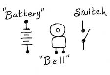
The subject of switching can be mind-boggling, until simple absolute rules are applied. There is always an electrical energy source, which we will designate the “battery”. This may actually be any one of, or even a combination of, energy forms. It may be a true battery, producing pure D.C. It may be a transformer, producing simple alternating current, or other complex forms of energy, i.e. square wave, saw tooth, etc. To make it perfectly simple, the energy source really doesn’t matter.
In the final analysis, there will be some device that is actuated or caused to function by the electricity. To further simplify things, this really doesn’t matter either. You take one single circuit at the time and you complete the circle. For the purpose of this discussion, we will designate the recipient of the energy as the “bell”. Then there is the “switch” itself. The form of the “switch” may vary from a huge oil immersion device that handles the 44,000 volt power lines, to tiny micro switches, and the literally thousands of different devices in between.
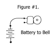
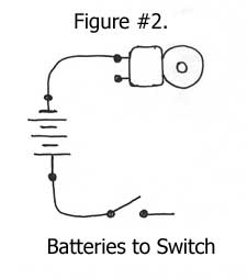
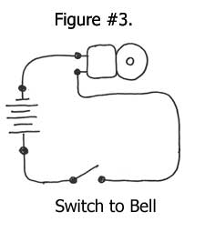
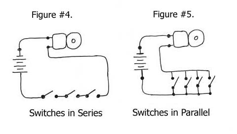
The simple, three step rule for any and every switching circuit is, Figure #1., you connect the “battery” to the “bell”. Figure #2, you connect the “battery” to the “switch”. Figure #3, you connect the “switch” to the “bell”. There are two variations on the basic switching circuit. The first is the series circuit, Figure #4. In this circuit, two or more switches are connected in series, so that the current from the “battery” must flow through one “switch” to get to the second “switch”, and then must flow through the second “switch” to get to the “bell”. There is no limit to the number of switches that may be connected in series, but the “battery” voltage must pass through every single “switch” to reach the “bell”. If one single “switch” is open, the “bell” will not ring. To simplify what would otherwise be a complex problem, you treat each successive “switch” as the “bell”, or receiver of the current, and “voila!”, the problem is resolved. On the Korean war era jet fighter plane, the “Banshee”, there were twenty-three limit switches in series, that all had to be closed to cause the retraction of the landing gears.
The second is the parallel circuit, Figure #5. For coping with switches in parallel, you simply modify rules #2 and #3, to make it switches (in plural instead of singular). For switches in parallel, throwing any single “switch” will make the “bell” ring. If you throw two switches in parallel, you must open them both to shut the “bell” up.
All of the discussion so far has been on how to make the “bell” ring. In almost as many cases as making the “bell” ring, we want to shut the “bell” up. In many, if not most, control circuits, the actual circuit that delivers the current to the “bell” is “latched” or a parallel “switch” is thrown across the circuit that “maintains” the current to the ringing “bell”.
- The “switch” may be exemplified by many different symbols.
- There are Single Pole, Single Throw switches ( S.P.S.T.) . Another very common version is the single pole double throw ( S.P.D.T. ) switch. All of the microswitches in the “Talyrond” (which was the original subject of this paper) are S.P.D.T. switches.
- N.C. indicates Normally Closed
- N.O. indicates Normally Open
In many circuits, several switches are placed mechanically in “tandem”. What this means exactly is that two or more switches are actuated by the same mechanical force. A good example of this design is the Double Pole Single Throw, D.P.S.T., switch that is usually used to turn the power to equipment on and off.
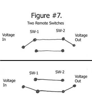
There is a cute little problem of switching that somehow gives most people a hard time. We want to turn a device on or off from either of two remote locations, both a distance from the device, and we want to do it economically. Use the basic formula, but look at it in a different light.
By using two simple, single pole double throw S.P.D.T. switches and only two wires, the mission can be accomplished. Just think of the two wires as separate circuits, and use the battery to switch, switch to bell rule and you have it. (See Figure #7).
Ladder Logic
Briefly, what is “ladder logic” or a “ladder diagram” for electrical switching? This system is applied to circuits when there is at least a fair amount of complexity, and a single motivating voltage. In this method of drawing an electrical circuit, there are “rails” and there are “rungs” between the rails just like a step ladder. The vertical “rails” are the two poles of the input voltage, and each “rung” is a single complete element of the overall control circuit. The “rungs” are the “switch” and the “bell”.
By stacking the elemental circuits between the two poles of the power source, very complex control circuits can be designed with relative ease. One leg of the power source is usually grounded to the frame of the machine. This leg is always drawn as the right hand rail. The direct connection of the “battery” to the “bell” is always shown on the extreme right hand side of the ladder diagram.
An overall machine control circuit is very complicated with all of the interrelated circuits opening and closing, of being latched and unlatched. By placing the interrelated components of each branch of the control function on a single horizontal line or rung between the two power supplying rails, visualizing and trouble shooting each circuit becomes child’s play.