Bal-tec™ Home The Kinematic Cook Book
The Kinematic Cook Book
Quick Review
Here is a quick review of the entire subject of kinematic couplings, from the most mundane principals to some that sophisticated practitioners may find enlightening.
Kinematic couplings are a concept not a dogma. A kinematic coupling is a separable joint between two members of a mechanical system. It locates and connects the two separate members together. This joint may include electrical and or optical interfaces.
Simply put, there are six degrees of natural or rigid body freedom, i.e. potential movements in any mechanical system. Many, if not most kinematic couplings are not designed to eliminate all of these six degrees of freedom.
There are three linear motions or degrees of freedom. Forward and back, which is usually referred to as motion in the "Y" axis. Motion from side to side is "X" axis motion. "Z" axis motion is up and down.
In addition to these, three linear motions, there are three rotary motions, one around each linear axis. There is "Pitch" around the "Y" axis. Rotation around the "X" axis is "Roll". The system can also "Yaw" around the "Z" axis.
Unfortunately our rigid body may not be as perfectly rigid as we would like. Any flexibility, i.e. bending of the platform or the body itself, are not natural degrees of freedom; but may play a major role in the location, error budget, of a given kinematic coupling. It must also be remembered that the Hertzian elastic deformations of the contacting elements are major contributors to the rubbery constituents of the platform.
In order to minimize these bending errors, extreme care must be exercised in both the physical design and the choice of material, for the platform itself as well as for the physically contacting elements.
The use of outboard posts or struts to support the kinematic elements is especially hazardous. The weakness or results of projections outside the mechanical envelope of the kinematic platform is severe and unexpected rotational moments whose magnitude will multiply rapidly with their distance from the couple. In many cases, there may be no design choice; but what can usually be done is to double or triple the breadth of these projections and or add stiffening ribs to reduce flexure.
Material Choice
Choosing the best platform material will be based on many factors that may include magnetic, electrical, and chemical as well as the physical properties of the material. The final choice will be based on the minimum total cost of construction that will yield all of the desired results.
Aluminium
Aluminum metal is widely, used for kinematic platform construction. This is based on its lightweight, ease of machine ability, and ready availability in a wide variety of forms. Its magnetic transparency may also be an important consideration for using this material. Abundant stiffening ribs may be required to overcome its very low Young's modulus of elasticity (stiffness), which is only 10,000,000 P.S.I. The oxidization of aluminum, with its potential generation and release of turbidity, can be a major problem in clean room applications. This problem can be eliminated if the entire aluminum platform is electroless nickel-plated.
300 Series Stainless Steels
A 300 series stainless steel may seem like a much better choice as a platform material than it actually is. Outside of their outstanding corrosive resistance, there is very little to recommend this family of materials. These steels have a bad tendency to be severely distorted by machining stresses. Because of their high chrome and nickel content, these materials are quite expensive, but the real downside is that their Young's modulus of elasticity (stiffness) is only 20,000,000 P.S.I.
Mild Steel
Mild steel is seldom the first choice for a kinematic platform, but it is actually one of the better materials. The amazing stiffness of ordinary steel, at 30,000,000 P.S.I., is three times as stiff as aluminum and a full one third greater than 300 series stainless steels. Hot rolled mild steel has good machinability with very little stress related distortion. Mild low carbon steel is very weldable. This excellent weldability makes construction of complex kinematic structures that are made of this material a simple matter. It is highly magnetic, so it is inexpensive to hold down for surface grinding which produces high quality reference surfaces. The high magnetic permeability of mild steel provides a good attraction for magnetically preloading the platform. It is the lowest cost material and it is readily available in a wide variety of forms. The major down side to using mild steel is its lack of corrosion resistance. This can be easily overcome by the inexpensive electroplating application of a thin layer of zinc or nickel.
Cast Iron
Cast Iron has many of the properties of steel, but its stiffness is only 20,000,000 P.S.I. Its main use is in high production products where complex forms can be made an integral part of the as cast design. It has good vibration damping properties. It is highly magnetic. It has good machinability.
Hybrid Materials
A seldom-used, but powerful ploy is to use hybrid construction of the platform. By incorporating stiffening ribs made of cemented tungsten carbide or aluminum oxide ceramic, sandwiched into inexpensive and easily machined aluminum structures, high performance platforms may be economically constructed. In this way the best properties of both materials can be economically maximized.
Carbon Fiber
Carbon fiber composites have given excellent results experimentally, but their extreme cost and the difficulty of precision machining have relegated this material to the realm of exceptional need. This material is extremely stiff and very light weight. Unfortunately, these materials are very hygroscopic, so they can change form due to out gassing, through contact with liquids, or even changes in room humidity, unless the material is well sealed.
Ceramic
Aluminum oxide ceramic is potentially the ultimate selection as a kinematic platform material. With a Young's modulus of elasticity in a realm that is twice that of steel, it is the stiffest practical material available. It is very lightweight. It is the ultimate in a corrosive resistant materials. It is entirely non-magnetic. This material has a high dielectric constant and is an excellent electrical insulator. The down sides are that the raw material is very expensive, and in the fired condition it can only be machined by diamond grinding. This material is very friable. It can be chipped or cracked by moderate impact.
Back To The Basics
Getting back to the basics, a device that fixes any ones or all of the six degrees of freedom without fostering any over constraint, causing strain, is a kinematic coupling. It should again be emphasized that many if not most kinematic couplings are not used to constrain all six degrees of freedom. As kinematic couplings are a study in "constraint" without "over constraint", some definitions, or understandings, are in order. The old rule that a body in motion will remain that way unless acted upon by an external force, is at the heart of constraint. Constraints will fix the location of a body against tensile stresses, axis by axis and will hold the body in this end position against all axial tensions, that are within the physical parameters of the couple. If these physical limits are exceeded the kinematic coupling will literally pop apart. This phenomenon is widely used in torque wrenches and C.M.M. probe heads among others.
I haven't found too many people who truly understand kinematic constraint and many fewer that comprehend over constraint. As a concept, expressions like: "excessive, or too much, or greater than required," don't really make it. All of the constraints that work in well functioning kinematic couplings are points of contact or at most extremely small areas of contact. They are not lines of contact, and they are not areas of contact.
For better clarity, let us site some common widely used couplings that are not kinematic, because they are over constrained. Two flat surfaces in horizontal contact will restrict three degrees of freedom, but they are not kinematic, because they are over constrained. They will fix the Z-axis and stop all pitch and roll. This will still allow linear movement in the X and Y as well as rotation in Yaw. Two prismatic surfaces in contact are not kinematic, for the same over constrained reason. Combinations of prismatic and flat surfaces in physical contact are not kinematic. The most common of these is the so-called geometric way, which has male and female vees and two flat surfaces that are in simultaneous contact. This system restricts five degrees of freedom allowing movement along one linear axis only.
High quality functioning of any of this type of device requires elastic compliance, more commonly referred to as elastic error averaging. The merits of these devices are their huge load carrying capacity and smooth precise movement. Although these previous configurations are widely used and very functional, they are not kinematic because they are over constrained by their large areas of contact. Separable bodies that are bolted together or bolted and pinned together, although it is a widely used and very functional practice, are not kinematic. Pins in holes or pins in slots are another example for the same reason. A matching male and female conical body in physical contact are over constrained and are not kinematic.
Deterministic
For a kinematic coupling to function properly it must be very deterministic. It must locate two mechanical bodies in exact relation to each other. It must keep them there under load and it must repeat this location after removal and replacement, time after time.
Forgiveness
The kinematic coupling is in general a very forgiving design concept. The angular and dimensional separation between the individual kinematic elements on the same platform is not critical. To demonstrate this, at trade shows we built a test bed consisting of three Vee block and three spheres. It was arranged so that one of the Vee blocks could be moved off axis, by plus and minus fifteen degrees. When the Vee block was moved back and forth, there was no apparent change in the up and down (2 axis). The three fixed spheres simply realigned themselves back and forth along the Vees.
This same model allowed the three individual Vee blocks to be rotated off the axis of the kinematic bisector. Even when a single vee block, or all three of the Vee blocks are twisted way off the bisector axis, there is no apparent degradation of the coupling.
I think that the non-critical nature of kinematic couplings is a very important point and needs to be given greater emphasis. To be truly kinematic the system of constraints must be forgiving and anything that makes them otherwise is a travesty to the kinematic concept.
It makes it a great deal easier to understand kinematic couplings, if you think of them in terms of each one of the individual elements or couples in a kinematic system, not the complete end product. The most basic elements, in the simplest single kinematic couple, are a true sphere in contact with a really flat plane. To begin with, lets imagine that both the sphere and the plane have perfect geometry and that they are infinitely stiff. We have one point of frictionless contact that is completely self-aligning and will exactly fix or constrain one single degree of mechanical freedom. This means that freedom of movement will remain in all of the other five realms.
Now lets come back to the real world where no geometry is perfect and no material is absolutely stiff. A simple statement of fact, is that as soon as the two elements of a kinematic couple come into physical contact, there is Hertzian elastic deformation of the surfaces and the couple is no longer perfectly kinematic.
Hysteresis
Elastic drag or mechanical hysteresis is an every day reality in kinematic couplings. It is the largest single factor affecting repeatability, in an otherwise well designed system. It is a matter of fact, that the component parts of a kinematic couple are all like gelatin at the molecular level. They approach each other, somewhat off axis, then contact and elastically deform or comply until pent up tension causes slippage and this stick and slip phenomena happens over and over again, until the couple comes to final equilibrium. After the final movement occurs, the entire system is still left in a state of off axis stress due to pent up elastic deformations. With this reality in mind, it is easier to appreciate the need for good geometry, a good surface quality and the highest possible stiffness as our means of controlling these elastic deformation causing hysteresis and therefore the repeatability of any given design.
To Review
From the standpoint of repeatability or accuracy, there are fundamentally two controllable variables for any given design and materials. The first is the geometric accuracy and surface texture of the elements, and the second is the stiffness or resistance to surface distortion of the basic geometry's. The general category of geometric error must include all imperfections, all the way down to the molecular level.
As you can imagine, a hand-forged sphere wouldn't repeat as well as one precision machined on a lathe and a precision ground sphere would do even better. As we continue the improvement down to a lapped and then to an optically polished surface, the level of repeatability, "x", would potentially follow the improvement in quality all the way down.
Unfortunately, our old nemesis elastic deformation is a constant limitation. The same "x" potential relationship exists between stiffness or Young's modulus of elasticity and repeatability that goes with geometric errors.
If you read some of the literature on kinematic couplings, you will find recommendations that you tap the coupling with a wood pencil or that you include an electric door buzzer on the platform that you momentarily activate to normalize pent up stresses that are in the elastic realm.
To give the two systems their best chance for self-alignment, a good ploy is to use a single cable or string to lower the upper system into contact with the lower. This allows the two platforms to more easily self align as they come into physical contact.
Preload
The force (usually at right angles to the couple) used to hold the two elements of the couple in place is the "preload" and it is best supplied by gravity in the form of dead weight, although mechanical or magnetic preloading is sometimes a necessary approach.
Resonate Frequency
While we are on the subject of preload we need to allude to the effect of preload on the resonate frequency of a kinematic system. The most influential factor in achieving a high resonate frequency in a kinematic system is usually the stiffness of the contacting materials but not far behind this will come the preload that is the stabilizing force applied to the system. For a given value of vibratory energy the amplitude of the vibration at low frequency will be higher than the same amount of energy at higher frequency. Every time the frequency is doubled the amplitude goes down 50 percent.
Contact Materials
If we look at the gambit of practical materials, for the physically contacting elements. From plastics with a few thousand pounds or at most a few million pounds per square inch young's modulus to aluminum, at 10 million, to the 300 stainless steel at 20 million, to carbon steel at 30 million, on to cemented tungsten carbide and sapphire at 100 million up to diamond at 600 - 900 million P.S.I. it is easy to comprehend how the stick and slip syndrome is reduced in direct proportion to the increased stiffness of the kinematic elements.
Because cost is usually a serious consideration in the design of all kinematic couplings, the more expensive, more exotic crystalline materials, ceramics and cemented metallic carbides will find restricted use.
We have discussed the importance of stiffness and the quality of geometry. The next step is to understand the effects of the nature of the geometry on repeatability and load carrying capacity. When it comes to repeatability between the different elements of a kinematic couple we have to think in terms of the "slippery slope", between the elements. The most underrated and misunderstood factor in kinematic couplings is the slope or rate between the kinematic elements. Slippery may be a colloquial term, but it is an extremely important factor in kinematic couplings. An analogy might be a ski run. The slope or angle of the grade is the first parameter and the nature of the materials in contact i.e. the waxed ski and the show is the second. The coefficient of friction between the two materials is one of the factors involved in a kinematic coupling also, but the ability to use materials with ideal coefficient of friction, such as tin, silver, or PTFE is severely limited by their undesirable physical properties. What we can do is to enhance the slipperiness to the n-th degree by improving the surface quality of usable materials to the highest level possible. We find that the bottom line in material selection for kinematic applications ends up being cost driven. Even with their high stiffness, that so greatly reduces elastic compliance, only fifteen percent of applications can afford cemented tungsten -carbide or ceramic, and only one half of one percent end up using diamond. Even though the kinematic qualities of these materials are fascinating, their actual use in end products, even in research and development, are few and far between.
This is probably as good a place as any to get practical and discuss real world materials for the contacting elements of kinematic couples. We need slippery materials that are stiff, strong, hard, wear resistant, fret resistant, corrosive resistant and will economically take an excellent surface finish, but at the same time they must still be inexpensive. All of these parameters can only be met by a high alloy steel. This steel will need lots of chrome for corrosive resistance and slipperiness, with high carbon for hardness and a touch of this and that for grain refinement and hardenability. What we end up with is a pretty good compromise in the Martensitic stainless steels. By spherodize annealing the raw material, the grain size of the individual crystals of this very high chrome, high carbon stainless steel can be driven down to the point where they are off the normal metallurgical scale. Using these high alloy materials we end up with an extremely fine-grained, corrosive resistant steel that can be hardened to 58 HRC (Hardness on the Rockwell "C" scale) or more and can be commercially lapped to a total surface texture that is well below one microinch (25 nm) Ra.
Fretting
At this point we have another window of opportunity to discriminate important information related to kinematic couplings. Fretting is a dirty nasty problem. Fretting is a fact of life for kinematic couplings. For the small area of contact with the resulting extreme loading there is no opportunity for lubrication. When using reasonably sensible materials and rational designs you don't get elephant trunks erosion, zippers, or galling that are so much a part of the literature on fretting, but the fretting that we do get is a major limitation to the use of kinematic couplings. Some of the readily available commercial components that would seem to provide cheap hardware for kinematic couplings are disasters in the making. Commercial ground only dowel pins are high carbon steel components that will start fretting the first time they are engaged. Commercial bearing balls will do the same, especially if they are used in conjunction with carbon steel dowel pins. I have read a great deal about fretting, but my personal experience with the fretting of kinematic components, that is based on long years of empirical experience, gives me my most valuable insight into the problem. To start with the component parts of kinematic couplings are under moderate to heavy load.
When two well-finished pieces of ferrite based materials come into intimate contact under conditions of Hertzian elastic stress, unusual things happen quickly. We are looking at slippage between two elastically deformed surfaces that are chemically active but relatively dry. When this happens simple chemical reactions occur on a molecular level. Surface temperature in the first few molecules reaches a high level and chemical by products are generated in the form of oxides of ferrite and other elements. This is evidenced by the reddish brown turbidity that is always generated in the early stage of kinematic fretting. These corrosion byproducts aren't of any serious problem by themselves, but the degradation of the surface quality, with the subsequent loss of slipperiness is a major issue. Trying to get away from this problem by using nickel or copper based materials has been a total failure due to the instant cold welding (small scale galling) that occurs at only moderate loads. The high levels of very hard, very low friction chrome carbides in the matrix of the Martensitic stainless steels greatly reduce; but cannot entirely eliminate this fretting problem. The fretting problem of Martensitic stainless steel is rated at one tenth that of hard, high carbon steel. Honestly how do we actually know what is going on at these molecular interfaces?
For a better understanding we need to take a quick side trip to a situation where we have a similar set of conditions but with much more pronounced indications of the effect of hard metals rubbing each other. When the bicycle became a popular mode of transportation, the demand for a smoother ride required rounder balls. Mr. Hoffman developed the modern ball-grinding machine. This machine basically rolled a lot of balls, at the same time, between two plates. One of the side effects of this grinding process is that the hard steel balls rub against each other occasionally. At the very low speed that these machines run you wouldn't expect this to be any problem. The unbelievable results of this slight rubbing create, "Hoffman" lines on the balls. These lines are invisible optically and even interferometricly.
A dilute solution of nitric acid in alcohol (5% Nitol solution) will etch a well-prepared piece of hard alloy steel a dark gray. When hard alloy steel balls that have contacted each other on the roll are etched, white lines on a dark background show up. The slight rolling contact between the balls actually raise the immediate surface temperature of the balls well over 1500 degrees Fahrenheit, and then the mass of the metal balls super cools this very thin surface layer leaving the white untempered Martensitic lines. Removing as little as fifteen microinches of material from the ball surface will eliminate the white lines. This scenario isn't very different from the sliding motion between contacting kinematic surfaces, when they are placed under load.
Teeny Tiny Kinematic Couplings
There is increasing interest in very very small, highly accurate kinematic couplings. The physical parameters of a really small design are something of a problem, but when this is combined with the requirement for nanometric repeatability, the design requirements get really sticky. Prismatic vee blocks or a vee block and a cone are out of the question for the smallest designs. When you get down to a ball diameter that is one millimeter (0.040 inches) or even one half of that, the only thing that we can get to work is three sets of two parallel cylindrical vees in one platform with three partially embedded balls in the other platform.
The design scenario plays out something like this. The two cylinders, which are about the same diameter as the balls, but many times longer, are epoxy glued into a shallow, narrow, trench that is machined somewhat deeper than one half of the cylinder diameters. The two corners of the trench are wet with the epoxy glue and the two cylinders are put in place. Another cylinder of the same diameter is placed in the center on top, and the three components are clamped while the epoxy glue cures. Small diameter Tungsten Carbide balls are inexpensive and should always be used as the spherical components. The tiny diameter balls are glued into three spherical recesses in the surface of one of the platforms.
A small diameter Tungsten Carbide ball applies such a high load that a tiny drill point, machined into the surface of one platform, can be turned into a high quality spherical recess by just forcing the ball into the surface of any ductile platform material, with a press of some kind. Throw this ball away after one use because it will be permanently deformed by the applied force. The three load balls can then be epoxy glued into these three spherical recesses. The balls should be preloaded while the epoxy glue cures. The epoxy glue may need to be warmed well above room temperature to reduce its viscosity, so that it can be applied to these very tiny surfaces. In addition to reducing the viscosity, warming the epoxy glue will greatly reduce the curing time and it will dramatically reduce the pot life of the glue, so this work must be done quickly. A small diameter piece of piano wire is an excellent tool that can be used to apply the epoxy glue to the recesses in the platforms.
Pseudo Kinematics
There are a number of very effective coupling designs that are not truly kinematic. If the flat plane in contact with a ball is split, and the two sections are inclined, we get a vee block. If we continue to incline the two planes, we will get more and more positive constraint of the ball. If we incline the two surfaces until they are perpendicular to the base plane and have the same spacing as the ball diameter, we have a device that will restrict two degrees of freedom. This doesn't seem very impressive until we pay notice to the fact that the bottom of the sphere will end up resting on the base plane that supports the two perpendiculars, so we get one more degree of constraint. If we machine a much larger spherical radius or even a flat plane on the bottom of the sphere, we get a device that is very deterministic, along with huge load carrying characteristics.
If we take a ball in a conical cup with its three degrees of constraint, and decrease the angle of the cone we will get a more and more positive constraint of the sphere. If we incline the included angle of the surface until it is zero degrees, we have an internal cylinder. If this I.D. cylinder is the same diameter as the ball we have a device that will constrain two degrees of freedom. Without repeating all of the details of the previous example, with the sphere resting against the base plane, we have a device that will very deterministically constrain three degrees of freedom and have enormous load carrying capacity.
It should be noted that both of the above couples constrain pitch. When they are used together, there is still complete freedom in the roll axis that will require a third couple if constraint of all six degrees of freedom is required.
To eliminate backlash when the mass of these devices tries to move and elastic deformation occurs, a small preload should be placed on the ball. This mechanical bias is provided by making the dimensional spacing of the two parallel flat surfaces slightly less than that of the ball diameter, and by making the inside diameter of the cylinder slightly smaller than its matching ball diameter. We are in effect providing a light press fit.
We might say that neither of these devices are truly kinematic because they are over constrained, but that might not make the best arrangement when you allow for the effect of elastic deformations of a classical kinematic system that is caused by a heavy applied load.
Screws And Nuts
Using threaded screws and nuts for preloading the Kinematic system can be a viable technique.
There are three obstacles that must be addressed for successful applications. The "X" axis and "Y" axis misalignment between the thread axis and the top of the platform must be compensated for. The upper platform should have sufficient clearance around the screw thread so that there is no chance for physical contact. The thrust washer on top of the platform must be a loose fit around the screw thread so that it cannot bind.
The second obstacle to overcome is to compensate for any alignment errors in pitch and roll between the thread axis and the top of the platform. This can be accomplished by inserting a spherical tilt between the thread axis and the top of the upper platform. The simplest design will be to use a truncated sphere with a through hole that is mated with a heavy washer, that has a matching spherical cup.
The final dilemma is to decouple the torque from the axial clamping force that is caused by the rotation of the clamping nut. This can be accomplished by inserting an antifriction thrust bearing between the clamping nut and the spherical tilt.
It must be realized that the leverage provided by a screw thread and nut, will provide an extremely high clamping force that is a large multiple of the torque, applied to the clamping nut. In order to control and repeat the substantial Hertzian elastic deformations of the point contacts throughout the Kinematic system, the end position of the clamping nut must be repeatable. This can be accomplished by simply engraving a clocking mark on the top face of the clamping nut. The rotary position of this line is set and will then repeat the clamping force to a high degree of accuracy.
Spring
Although there will be some pliability or elasticity in the end position of the clamping nut, there may be good reason to increase this by adding a compression spring in line with the clamping nut. This spring can be inserted anywhere below the antifriction thrust bearing in the chain of error compensating devices.
Capture
Capture is a rather obvious requirement of all Kinematic couples. How far away from home position can the two platforms be and still fall into the target area, so that they will self center to home in, on the end position. If the engagement of the two platforms is to be entirely automatic some form of two-dimensional rail or guide system may be required. This loose fitting auxiliary system acts as a funnel to guide the two subassemblies into full contact.
Sub - Miniature Kinematic Couplings
Nano scale mechanical systems are being constructed that use Kinematic couplings, to accurately assemble sub-miniature system components. From a real world standpoint, just how small is it now practical to go and what form of construction is used? The smallest system that we have participated on had 0.015-inch (.38mm) diameter tungsten carbide balls against pairs of 0.015-inch (.38mm) diameter, ground and lapped, hard Martensitic stainless steel cylinders. To increase the load carrying capacity, we speculate, that cylinders with precision lapped flats could be assembled in a shallow trench.
Magnetic Preload
When dead weight can't be used or when extra physical bias is required to balance an off axis load, the best approach may be the application of magnetic fields.
A magnetic field can also be used to supply a very compact force that will drive up the resonant frequency, of the platform, by increasing the elastic compliance of the Kinematic contact surfaces. Magnetic fields are soft. They are cushy. They are very forgiving. A magnetic field has a shape and consistency very much in the form of a magnetic water fountain. Like a water fountain, the magnetic fields shape and pliability allow for considerable latitude in geometric placement and attitude.
Being able to adjust or tune the magnetic force is another powerful feature of this approach. By building super strength, rare earth magnets, into high permeability steel cups, that are threaded on their outside diameter, a very versatile approach to providing adjustable magnetic fields results.
Aspect Ratio
Most of the literature on Kinematic couplings somehow assumes that the designers have complete control over all parameters of the Kinematic system. Quite the contrary is true in the real world. As designers we would like a nice equilateral system with the three spheres spread far apart and at perfect 120-degree locations. The center of gravity, of the payload, would be placed axiomatically on a plane thru the centers of the spheres or lower. What we actually get is an envelope with has an aspect ratio that is two to one or five to one or even ten to one, and a payload that has a center of gravity that is way off to one side and far above the axis of the coupling. When the aspect ratio is out of proportion, there is a weakness in the rotational stability of the roll motion. Rotation in the Yaw motion is also less deterministic. It is not as crisp due to the longer lever involved. If all Kinematic couplings were ideal the only Kinematic hardware that would ever be needed would be three vee blocks and three spheres.
Split The Couple
A powerful tool to help cope with an out of proportion aspect ratio is to split the coupling. Instead of locating the individual couples as far out on the corners of the platform as possible, which would be normal practice, locate one of the couples on one edge in the center of the coupling and the other two on the opposite corners. What this does in effect is to split the coupling and reduces the aspect ratio by one half.
Power
Here is a kind of in-house concept that we call the "power of the couple". The power of the various couples varies considerably. The power of a couple is a badge of merit. A higher power is a composite of the self-centerability and the dynamic stiffness with a high resonant frequency as a by-product. As the instabilities or weakness created by a large aspect ratio are rotational, more powerful devices that restrict these movements will result in a more stable platform. With some concept of the power of the individual Kinematic couples in mind, let's tackle the off center load. One of the easiest and least expensive ploys, to increase the power of a given couple is to spread the individual elements of the couple apart so the contact angle with the sphere is 120 degrees or slightly more. This will maximize the power of the couple, by increasing the self-centerability, but beware that it will also reduce the load carrying capacity. A three constraint couple is the most powerful because it is the stiffest due to the local cluster of constraints, it has good self-centerability, and it has the highest load carrying capacity of any couple, so to the best of our ability, we should place the maximum proportion of the load over it. For similar reasons the two constraint couple is more powerful than the single constraint, so we place as much of the remaining load over it as possible. Then we use the single constraint couple to take up the balance of the load. By using this approach we do loose the highly desirable symmetry of the three vee and three sphere coupling, but we gain orders of magnitude in platform stability by using the power concept to balance the off axis loading.
Counterweight
A countervailing force, consisting of a high density mass, placed right on the deck of the platform, but well off center can provide the decisive feature, needed to cope with a very heavy off center payload. Using the same principals a magnetic force can be used to help equalize the off center loading.
Enough
There is another in-house concept that we call "Enough". "Enough" is mainly a financial consideration. Going for broke or pulling the plug, makes no sense when the actual results only require an ordinary Kinematic design. The simplest concept of Kinematic couplings is so powerful when compared with commonplace, over constrained methods, that the most mundane Kinematic design will suffice for most applications. In the world of over constraint, location within one thousandth of an inch (.025 mm) is good, five ten thousandths of an inch (.012mm) is great and two ten thousandths of an inch (.0005 mm) is the ultimate. In contrast, when you are working in the realm of Kinematic couplings, one micron (40 microinches is good, one microinch (25 nm) is outstanding and a few nanometers is pushing the envelope.
Thermal Sensitivity
The reaction of the Kinematic system to changes in temperature can be of great importance. Some of the variables involved in a Kinematic systems reaction to a delta "T" are quite obvious, but some are more subtle. The most obvious is the thermal coefficients of expansion of the platforms and the other elements of the system. One of the approaches to controlling the effects of temperature change is to use platform materials and the other elements that have a low rate of thermal expansion. Invar® and carbon composite platforms have low expansion rates, as do most ceramics. The standard stainless steel Kinematic elements have a 6.4 microinch per inch per degree Fahrenheit expansion where Tungsten Carbide has only 2.4.
Another approach is to get the change over with as quickly as possible. The response of aluminum to changes in temperature is both good and bad. Aluminum has a rather high thermal coefficient of expansion, that averages 12.6 microinches per inch per degree Fahrenheit. On the other hand, Aluminum is one of the very best conductors of heat, so the adjustments to temperature change is almost instantaneous. If the top and bottom platforms are about the same dimensional proportions and they are both made of Aluminum, the net result of a delta "T" will be almost no change in the position of the payload. The next and in some ways the most influential feature available to the designer is symmetry. By choosing a perfectly symmetrical design, any delta "T" will cause a uniform movements in all directions. The end result with a perfectly symmetrical system, will be that the original datums will shift little or not at all, during temperature swings. What this means, is that in temperature sensitive situations we should choose the Maxwell approach to Kinematic couplings, that uses three symmetrical vees and three spheres instead of the Kelvin system with it's asymmetrical cone, vee and a flat in contact with the three spheres.
The Wobble Pin
Isolating the driver from the driven in a one-degree of freedom system presents a challenge. In an ideal situation, the driving force will be on a centerline that posses through the center of gravity of the system's mass. A sphere against a flat plate is a good approach, but any off axis translations can resolve into distortions of the truly straight line of motion for the driven. A secondary carriage that is driven and in turn drives will give the required buffer, or a simple wobble pin can be used. By providing a non-influencing outlet for off axis forces so that they do not result in distortion of the straight-line motion of the driven carriage, the desired result can be achieved. The wobble pin is typically a relatively long slender rod, with a high quality spherical radius on each end. These spherical radii are coupled to the driver and the driven systems thru a pair of three constraint couples. These couples can be a conical cup for low performance systems, a three ball couple for high performance systems at low load, or a trihedral clamp for high performance high load systems. All of these Kinematic devices are discussed in detail in other parts of this paper. In low load systems, the wobble pin is an effective way of decoupling a rotation of the driving mechanism from a non-rotating driven element. It is often reported that the wobble pin can only be used in compression, but the fundamental concept can be applied in tension as well. By using a sphere that is larger in diameter of the pin than the cylindrical diameter, the three constraint coupling can be placed on the back sides of the spheres and this off axis correcting mechanism will work in tension. Although a wire constrained at both ends is technically a flexure, it will still fulfill the essence of the wobble pin's function in tension.
Hard Stops End Stops
These devices require the same quality and physical property requirements as conventional Kinematic components. They are usually used to mechanically define an end point that often constrains a dynamic force. When a moving mass is brought to a dead stop, dynamic shock is an additional factor that must be contended with. Dead stop systems generally consist of a spherical surface coming into contact with a flat surface. The contact point of the two elements of this system, must be on a centerline that passes through the center of mass of the moving system, or an upsetting force will be generated. The instantaneous shock loads imposed on the dead stop elements can be considerable, so the diameter of the sphere is usually made quite large. The spherical diameter of our standard device is one and one quarter inch ( 1.250", 31.77 mm) diameter. The selection of the materials for the sphere and the flat elements requires special attention. Like most other Kinematic elements, the number one material quality required of a dynamic end stop is stiffness. This property is a very serious requirement in order to avoid the possibility of brinelling.
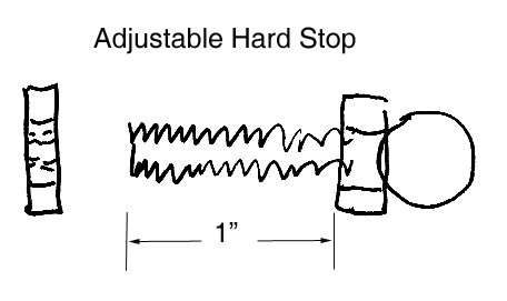
To assure repeatability, excellent qualities of geometry and surface texture are obvious requisites. This is especially true if the repeatability of the end position is to be measured in micro inches, or even nanometers. At moderate force levels, a hard Martensitic stainless steel material may be used for both elements of the stop. For coping with high to very high levels of force, tungsten carbide elements, or a hybrid combination of a tungsten carbide sphere and a hard stainless steel flat are the general approaches. The hard stainless steel version is our part number HS-125 and the tungsten carbide version is HS-125-TC.
The body of the standard off the shelf spherical device is constructed of corrosive resistant 300 series stainless steel. It has a one-quarter inch ( 0.25", 6.35 mm) diameter shank, with 28 threads per inch (SAE standard national fine). In order to allow for adjustment, a rather long threaded shank that is one inch long ( 1.0", 25.4 mm ) is provided. A thin stainless steel jam nut is supplied with this device. Shorter versions of this part can be supplied on special order. To provide for longitudinal adjustment of the hard stop by rotation or to lock it in place, there is a hexagon provided, adjacent to the spherical contact. For special applications requiring clean room compatibility, high vacuum, electrical or magnetic properties custom made components featuring ceramic contact materials and exotic metal combinations will be quoted. A drill and tap kit (our part number DT-1/4-28) is available for our non English System customers overseas. A wide variety of the flat components for use in hard stops will be found under flat components in the Kinematic catalog 105B.