Bal-tec™ Home Micro Inch Positioning with Kinematic Components
Micro Inch Positioning with Kinematic Components
Introduction
It is said that precision engineering actually began with the discovery of the kinematic principles. A kinematic coupling is simply the most accurate method of joining two mechanical elements. It is an elaboration of the three legged stool concept. The three legs of a tripod will exactly match the surface that they contact, without any wobble. The fundamental of kinematic coupling design is to selectively eliminate each one or all of the six degrees of mechanical freedom that any physical body has. These six degrees of freedom consist of three transitional and three rotational movements. The three transitional movements are side to side, front to back and up and down. These are usually referred to as movements in the X, Y and Z axii. The three rotational movements occur when the mechanical body pivots or rotates around any one of the transitional axii. These rotational movements are referred to as roll, pitch and yaw.
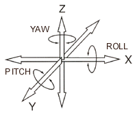
The basic requirements for an accurate location system is that the bodies must be rigidly fixed in relation to each other; but without any over constraint, that is without any undue stresses. The first recorded use of Kinematic couplings was in instruments and clocks more than a century ago. The original kinematic design consisted of three combinations of elements. The first was a sphere and a flat plane which restricts a single degree of freedom. The next combination was a sphere and a Vee which constricts two degrees of freedom. The last was a sphere and a conical cup or socket which restricts the last three degrees of freedom.
It should be emphasized that many, if not most kinematic couplings are not designed to restrict all six degrees of freedom. Many times kinematic principles are used to precisely define the linear or rotary motion within a mechanical system. This is done by leaving one or more of the component parts free to move in one or more directions. As the accuracy requirements for location have increased, many innovative Kinematic designs have evolved.
<
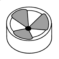
The conical socket or cup is a very difficult geometry to generate to a high degree of mechanical perfection. To improve the function of this hard to manufacture element, the surface of the cone may be truncated to leave three conical ribs.
A further improvement of this least accurate element of the system consists of producing three prismatic facets that are arranged to form a trihedral cup. This device is the Kelvin clamp. Three balls mounted on a bolt circle form a very high quality nest or cup to provide the highest quality replacement for the conical socket. As a further improvement, two accurate cylinders can be substituted for the somewhat limited accuracy of a machined Vee.
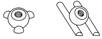
These developments have allowed Kinematic couplings to be produced that literally have sub-micron accuracy. The next developments were improvements in the economics of producing Kinematic Couplings rather than in their accuracy. A truly high quality kinematic coupling can be generated through the contact of six cylinders and three spheres or six spheres and three cylinders. There are many other combinations of spheres and other basic geometries that can make couplings which are easier and less expensive to produce.
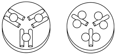
Several factors must be considered in choosing the design of a Kinematic coupling. One of the questions to be answered is; What is the required accuracy? Combinations of cylinders and spheres made of fine grain, hardened, stainless steel form an absolutely beautiful marriage for use with low to moderate loads. When these combinations are engaged, there is a phenomenal cushioned self alignment that brings the two halves of the Kinematic coupling or platforms into micro inch accurate positioning. This occurs even when the two systems are badly misaligned on initial contact.
Another question is what is the required load carrying capacity? As the load goes up, the flexing of the very narrow contact surfaces of the small spheres and cylinders, will cause fretting. Fretting is a rust like wear of the contacting surfaces caused by friction between the elastically deforming components.
Tungsten Carbide
When high to very high loads are involved, other approaches are required. The first step is to choose as large a spherical and cylindrical radius as possible. As the load increases even more the next step is to choose a material for the sphere that has the highest Young's Modulus of Elasticity possible. From a practical standpoint this choice is simple. The one readily available material that meets this requirement is tungsten carbide. It has a typical Young's modulus of Elasticity that is more than three times that of steel. Steel is in the range of 30,000,000 pounds per square inch and tungsten carbide is 98,000,000 pounds per square inch. Tungsten carbide is not too expensive, it can be ground with a diamond wheel and it is electrically conductive enough to allow
As the load goes on up, you simply need greater wrap around i.e. increased contact area between the elements of the coupling. The next step up would be to use multiple Vee-Blocks, where flat surfaces take the place of the cylinders. Tungsten carbide on tungsten carbide is not always a desirable combination so the first choice would be tungsten carbide spheres on hard stainless steel Vees. The additional wrap around of the two flat surfaces of the vee will greatly increase the load carrying capacity of such a coupling. The next small step to increasing the load carrying capacity is to go to ceramic or even diamond surfaces on the Vee-Blocks.
Gothic Arch
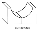
A comparable improvement can be achieved by using hard stainless steel elements configured in the form of Cathedral or Gothic arch Vee-Blocks. The final step in a classical kinematic coupling is to build the cathedral arch Vee-Block from ceramic.

By using a toroid ( donut shape ) of very large radius to replace the sphere, the wrap around can be increased even more, but machining high quality surfaces in these configurations approaches impracticability. A similar effect can be be achieved by combining two rather thin slices of a large diameter sphere mounted back to back to form a mock toroid. A similar approach can be used with the cylinders to greatly increase the load carrying capacity while maintaining the excellent self aligning properties of a cylinder.

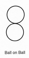
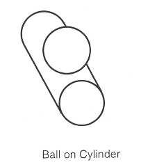
The surface texture of both components are of the utmost importance. Both waviness and micro finish must be of the lowest value or the surfaces will stick before they come to perfect mechanical equilibrium. In a sense, the surfaces need to be slippery so that they will mechanically self align before the final elastic deformation occurs as they settle together. Our experience indicates there is a gradual reduction in the accuracy of the union between the elements of the coupling as the progressive load carrying techniques are applied. As the radii are increased the accuracy gradually decreases with small spheres against small cylinders being the best and large spherical radii against cathedral arches being the poorest of the classical designs. Toroidal surfaces against flat prismatic surfaces gradually end up as over constrained designs. The least accurate are male flat prismatic surfaces against female prismatic surfaces in an over constrained pseudo kinematic design.
An additional question involved in designing a kinematic coupling is the metallurgical compatibility of the contacting materials. Ultra fine grained, hardened, high chrome, high carbon stainless steel is the best choice for both components under low to moderate loads. As loads increase, stiffer materials are required but it is good practice not to use mating materials with the same chemistry in high load situations. Under high loads the intimate contact of two identical materials can actually cause galling or cold welding. Ceramics and cermets have much less of this tendency. The techniques used for mounting Kinematic components vary widely to meet the many different parameters. Some of these variants are the cost of mounting, the load requirements for the mounting interface, the reliability, whether it's for prototype or production and whether the device is for temporary use or whether it is to be permanent. The simplest configurations use complete balls and cylinders. This is the least costly approach and it can work well in situations where loads are low and the profile height of the coupling is not important. Complete components are usually press fit, staked or glued in place.
Truncated Balls
Truncated balls and cylinders have one flat surface ground on them. They are only slightly more expensive than the complete components. They are usually glued or staked in place. Truncated components are more mechanically stable so they provide better reliability and higher load carrying capacity. The profile height of these components is usually one third less than complete balls and cylinders.

Electrical Discharge Machining (E.D.M.) a shallow recess in the flat surface of a truncated component provides a much better glue line. The remaining flat rim around the outside edge of the component is very mechanically stable. Adding holes in the kinematic components for location over pins will increase the reliability and the load carrying capacity without substantially increasing the cost. Threading the pin holes in the truncated and recessed components makes them much more versatile, increases their reliability, and adds to their load carrying capacity plus increasing shock or impact resistance. When building prototype or temporary structures, the screwed down components have the advantage of being removable for relocation or reuse.
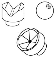
If slight wear develops on components of this design, cylinders can be reversed and spheres can be rotated. High load carrying Kinematic components, such as Vee-Blocks, often have precise appendages such as cylindrical bosses to increase the load carrying and shear strength of the joint. There are times when the Kinematic component can only be secured from the front surface. In this case the components are drilled through and counter bored from the front to allow them to be tied down by socket head cap screws.

Another important consideration in choosing the design of Kinematic couplings is the complexity of mounting the components on the Kinematic platform. When precision machining capabilities are readily available screwed or screwed and glued down components are excellent. In contrast, pinned and glued down elements are good and much less expensive and glued only construction is the most economical, but has the lowest load carrying capacity and is the least reliable. In some metrology applications, this technique is preferred because this design acts as a fuse to indicate overload or abuse. A good technique for assisting in location and to increase the load carrying capacity of glued only components is to machine a shallow recess to glue the components into.
Magnetically Assisted Kinematics
For prototyping or when precision machining capabilities are not readily available, excellent results can be achieved by clamping the two bases or platforms of the kinematic coupling together and then drilling and reaming coincident holes through both platforms on a drill press or even with a hand drill. The kinematic elements best suited for this approach are three Vee-Blocks with a cylindrical mounting tang and three spheres with a threaded hole part way through. Both of these elements can be rigidly mounted to the platform from the front surface or from behind. For production applications, a surface mounted version of the Vee-Block component without any tang can be used. Magnetically assisted Kinematic couplings can be a viable design option. There are two approaches to applying the magnetic force. The first is to mount the magnet axisymmetric so that the magnetic attraction pulls the sphere into or onto the coupling. Good examples of this is mounting a magnet in the center of a cone, in the center of a three ball coupling or between two cylindrical rails.
The other approach is to actually make one or more of the components magnetically attractive. The simplest of these is using the flat surface of a magnet as one component in the kinematic system. Another approach is to make the sphere itself out of a magnetic material with the pole in line with the coupling. A very functional design based on this approach is to place a powerful magnetic tube or ring between two spheres. The fields of the magnetic ring makes each one of the spheres polarized with the opposite magnetic fields. These two spheres will hold and align a cylinder anywhere in the 360 degrees all the way around the balls. In addition to the ability of these magnetically aided couplings to hold assemblies at angles that are not perpendicular to gravity, the magnetic field dampens vibration between the elements. The magnetic force will raise the resonate frequency of the assembly, making it much easier to isolate it from incoming vibration. The metrology frame of this measuring machine rested on the flat end faces of three large cylindrical post. Two precision lapped spheres with a hole through their center were rigidly mounted around two of these cylindrical post. The posts extended all the way through the spheres so their flat end faces continued to support the mass of the machine.

The first spherically clad post was precisely fit to the inside diameter of a lapped cylindrical ring with a 50 microinch (1.3 micrometer) interference. This cylindrical ring was securely attached to the machine base. The second spherically clad post was placed between the flat parallel faces of two precision lapped rails that were set to provide a 70 microinch (1.8 micrometers) interference. The two rails were securely attached to the top surface and at a right angle to a dovetail way. This right angled way allowed the entire metrology frame of the machine to be swiveled around the sphere inside the cylindrical ring and along a line between two rails for alignment. The two interference fits used in this design are obviously over constrained which makes this design pseudo kinematic at best.
On the other hand, when the mass of an apparatus is applied to a conventional kinematic system there will be considerable elastic deformation of the component element of the system. Does this deformation constitute elastic averaging, thus voiding the kinematic pedigree? High quality positioning doesn't have to end where high load carrying capacity begins. If the angle between the faces of a Vee-Block are decreased, you will reach a point where they form a flat surface. If on the other hand the angles are increased, you will reach a point where there are two parallel rails. At what point does it cease to be a Vee-Block? The same pattern is true as the angle of conical cup is changed. It can become a flat plane or the walls of a cylindrical hole. I think that it is high time for us to stop being kinematic purists and look instead at productive results of any innovative designs.
A Typical Application
An example of a very recent application of the Kinematic coupling was for positioning a huge silicon crystal in the x-ray beam of a national lab synchrotron. This liquid nitrogen cooled crystal is used as the monochromator. The requirement for heavy load carrying capacity and very exact repeatability was achieved by using three large tungsten carbide balls and six cylinders. These truncated balls and cylinders were drilled and threaded by Electrical Discharge Machining. The three balls sit in three vees that are formed by the six large diameter tungsten carbide cylinders. One surface of these precision lapped spheres and cylinders was diamond ground flat.
A good example of a Kinematic coupling that doesn't restrict all six degrees of freedom is the Cantilevered Ball Bar. This device is used to evaluate the performance of Coordinate Measuring Machines. A Ball Bar consists of two very round spheres of exactly the same size securely attached to the opposite ends of a rather long rigid bar. The Cantilever Ball Bar design has additional support spheres just behind the master evaluation spheres. These two support spheres are held in Kinematic couplings that form an extremely rigid non-constraining coupling. The first support sphere sits in the Kinematic cup formed by three spheres. The second one sits in the cradle formed by two precision cylinders.

Are They or Are They Not Kinematic?
Some years ago we built a huge linear measuring machine that had to be aligned within microinches. The large load involved would have made conventional Kinematic design so large as to be impractical. The design we used was so simple that it probably isn't new.

Just how accurately will a Kinematic coupling repeat? We attempted to answer this question once and for all. If we accept the inter-atomic dimensions of a steel molecule at about three Angstroms, the outcome of our test places the number at about ten molecular dimensions or one nanometer, but like so many other state of the art attempts there are some funny things going on. The absolute measurement is time dependent, indicating that the surface of the steel part is viscoelastic. A simplistic explanation might be that the atomic binding forces are lower at the surface so it is more compliant, i.e. it actually has a much lower modulus of elasticity. Another explanation might be that the non contact capacitance gage used for the test is causing local heating of the test part, thus causing a local swelling of the surface. The sinking is linear with time until it stops so the heating explanation doesn't seem to fit. The kinematic mount used in this test consisted of two spherical diamond contacts of 0.125 inch ( 3.2 mm ) radius placed at a 120 degree angle to each other. The third contact was a flat gold plate. The sensor was a capacitance gage placed between the two diamond spheres. The test sphere was a hardened and lapped 1.00 inch ( 25.4 mm ) diameter stainless steel ball with a surface texture of .26 microinches (about 7 nm) Ra (Arithmetic Average). The sphere was raised up out of and lowered back down into the Kinematic coupling by a robot.
