Bal-tec™ Home Non-Kinematic Couplings
Non-Kinematic Couplings
There are situations where location systems that are not Kinematic should be considered or at least understood. Some of the alternative couplings will include the following.
1. A matching male and female cone can form a couple. If the angles of the mating cones are steep enough, the two halves of the joint will literally lock together so tightly that they will have to be driven apart. If the angle is flattened, we will reach a point where the two parts will easily separate. This arrangement is limited to on axis systems like lathe or milling machine spindles. The best conical surfaces are not very good, so considerable elastic distortion, with the associated over constraint is inevitable. ( See Figure #1. )
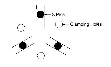
2. Three equally spaced slots, machined at angles with their axii pointing to a common center in one plate and three protruding pins that mate with the slots in the other plate. The repeatability of this system is limited by the accuracy of the machining. In clamping the two plates together the system is grossly over constrained. ( See Figure #2. )
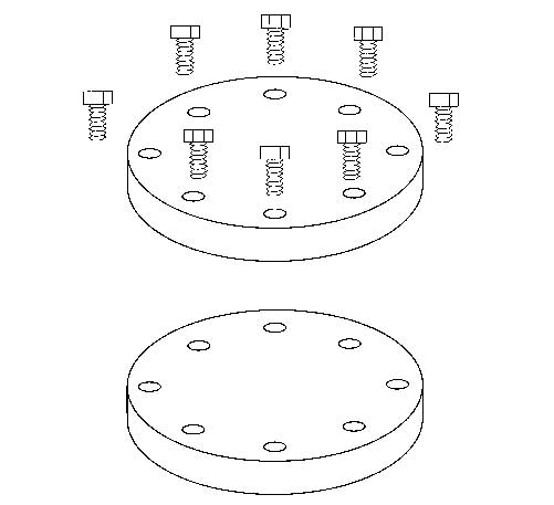
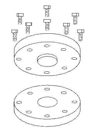
3. Two flat surfaces can simply be bolted together. The top plate can have clearance holes that match threaded holes in the lower plate or both plates can have clearance thru holes and a combination of bolts and nuts can be used for the clamping. ( See Figure 3A. ) A slight improvement in the location between two flat surfaces can be achieved by having a protruding cylindrical pin go into a matching cylindrical hole in the center of the plates. From the standpoint of precise location, this is probably the poorest commonly used system. This system must be highly over constrained to function. ( See Figure #3B. )
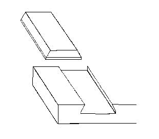
4. There are a wide variety of dovetail designs that can provide satisfactory location in some designs. If the location is to be precise, an extremely high degree of craftsmanship is required, to achieve precise mating of the many prismatic surfaces involved. This system is usually used, when precise movement of one part of the system in relation to the other is required.
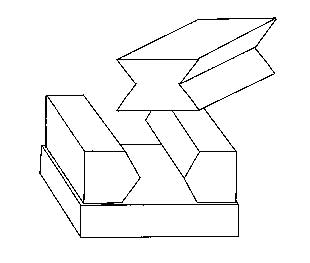
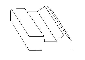
This is another system that is used when relative motion is required between the two elements of the system. To produce highly accurate motion between the two systems a very high level of skill is required in the manufacturer. ( See Figure #5. )
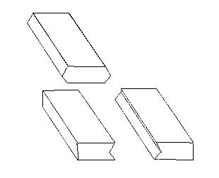
6. Three or four separate sets of mating prismatic vee and vee block surfaces are widely used in pallet type devices. These systems require extremely fine and expensive machining and even then their best locating ability is only 20% of a simple inexpensive Kinematic coupling. A high level of elastic deformation is required to achieve mechanical stability. ( See Figure #6. )
7. The most widely used system in precision manufacturing is three precision dowel pins fixed in one plate, that fit into three mating holes in the other plate. The accuracy of this approach is limited to about 20% of a simple Kinematic coupling and requires very expert machining. ( See Figure #7. )
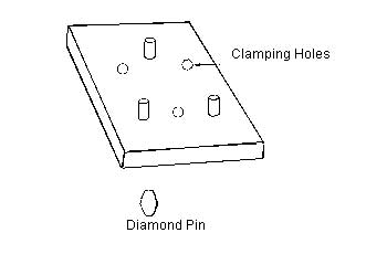
8. In order to reduce the sophistication of the machining required, for a three-dowel pin system, a very clever ploy called the diamond pin can be used in the above system. By using one solid dowel pin and two dowel pins with the sides ground off to form a diamond shape, good location can be achieved with less accurate machining. By pointing the remaining cylindrical spokes of the diamond pins in 90-degree directions, much more freedom of location is allowed. ( See Figure #7. )
We once ran a very sophisticated study for the U.S. Air Force to find out how accurately a dowel pin could be pressed into a hole. Without going into too much detail, the results were dismal. We ended up with pins that were precision lapped cylindrical within a couple of micro inches and cylindrical holes that were lapped like ring gages, but still the pins wouldn’t accurately locate in the holes. Beware of exotic claims for the repeatability of these designs, as we have found that the quality claimed, has very seldom, really been measured.
9. No discussion of exact constraint would be complete without some discussion of tapered pins. These clever devices have a very slight tapered angle that is elastically deformed to fit into mating tapered holes. In a typical application, two plates are mated in ideal position.
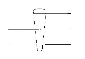
Two or more undersized holes are drilled through both plates and then a “taper pin reamer” is used to produce a single continuous tapered hole. The tapered pins are then driven into these holes with a hammer. Although this system is seriously over constrained it has about the same accuracy as the three-dowel pin system, but is much simpler and requires far less skill to produce. See Figure #9.
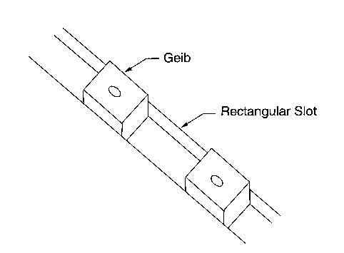
10. Another system called Gibing, which is most frequently used to restrict five degrees of freedom but can be extended to include all six degrees. It is widely used in machine tools, to locate accessory tools. The system consists of one or two rectangular slots with some tie down method like tee slots. Two or more rectangular blocks called gibes are closely fit into these rectangular slots to restrict the “y” and “yaw” axii movement, while the mating flat surfaces restrict the “z”, “roll” and “pitch” axii. This system is seriously over constrained by the clamping force. The overall accuracy is limited by the accuracy of the machined components. See Figure #10.
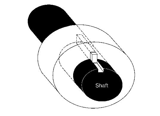
11. The key and keyway are similar in many respects to the geib system, and is another of the common constraint systems. The key is usually a single fairly long rectangular or square device that fits closely in two rectangular slots, one in each member of the bodies to be constrained. These slots are called the keyways. See Figure #11.
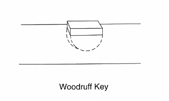
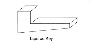
12. In addition to the conventional rectangular key, there is the Woodruff key, which is semicircular device that is embedded in one of the bodies and has a protruding tang that prevents relative movement of the other body. Still another key is tapered key that can be driven into full elastic compliance with the two members of the system. The key and keyway system are not a highly accurate system and are grossly over constrained by the clamping force that must be supplied. See Figure 12A.
13. Riveting is a semi-permanent method of coupling two parts of a mechanism. The rivet is passed through mating holes in the two parts of the mechanism, and the rivet is plastically upset. It expands to form an interface fit, thus rigidly coupling the two parts together. ( See Figure #13. )