Bal-tec™ Home Flexures
Flexures
A Flexure can be used to reproduce almost perfect linear or rotary motion or a combination of both. The length of travel of this very accurate motion is, however, quite limited. Flexures will produce these motions without any friction or hysteresis down to the sub-nanometer level, and they never need lubrication. A term often used to describe them is a flexural hinge. When you are trying to fathom the intricacies of flexural design, remember the word “hinge”. It indicates a rotational motion, which is characteristic of all flexures.
Catalog Flexures - Off the Shelf
Bal-tec is offering a stock line of off the shelf flexures and support hardware in a limited number of configurations and sizes. We machine our stock flexures by the Electrical Discharge Machining process, so there are no distortions or burrs and no pent up stresses. Each of the standard configurations is offered in high carbon blue-tempered and polished spring steel. This material provides the best overall properties of any economical, commercially available material. As this material is tempered at 900° Fahrenheit, all retained austenite is transformed into tempered martensite, so there will be no phase change to contend with.
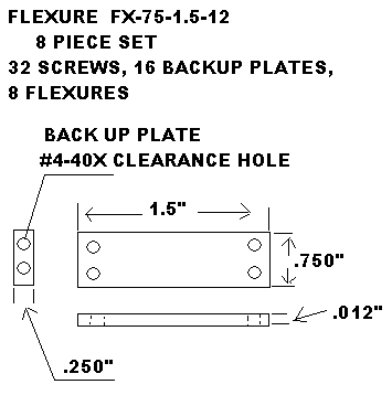
A wide variety of spring rates are offered in each physical design. This is achieved by producing the same part design in varying thicknesses of 0.004” (0.102mm) 0.006” (0.150mm) and 0.012” (0.305mm)”. These off the shelf flexures are sold in sets of eight, except for the long narrow rotary flexures which are sold in sets of four identical pieces. All designs are sold in bulk for production applications. Each set of eight flexures includes sixteen rugged backup plates that have one surface precision flat lapped to maximize metallurgical contact with the spring flexure. One edge of each backup plate is well radiused to blend tangent to the flat lapped surface. Each set also includes the proper number of socket head cap screws for rigid mounting. See Table A.
Each set includes: 8 Spring Steel Flexures, 16 Backup Plates and the proper number of socket head Cap Screws for mounting.
| Set Part # | Width | Length | Thickness | Socket-Head Cap Screws | Backup Plate# | Price / Set |
|---|---|---|---|---|---|---|
| FX-25-1.5-6 8 pcs |
0.250” 6.35mm |
1.5” 38mm |
0.006” 0.152mm |
16 pcs #4-40x ¼ inch long 6.35mm |
BP-25 16 pcs. |
$86.00 |
| FX-25-1.5-12 8 pcs |
0.250” 6.35mm |
1.5” 38mm |
0.0120” 0.30mm |
16 pcs #4-40x ¼ inch long 6.35mm |
BP-25 16 pcs. |
$86.00 |
| FX-75-1.5-4 8 pcs |
0.750” 19mm |
1.5” 38mm |
0.004” 0.102mm |
32pcs #4-40x ¼ inch long 6.35mm |
BP-75 16 pcs. |
$98.00 |
| FX-75-1.5-6 8 pcs |
0.750” 19mm |
1.5” 38mm |
0.006” 0.152mm |
32pcs #4-40x ¼ inch long 6.35mm |
BP-75 16 pcs. |
$98.00 |
| FX-75-1.5-12 8 pcs |
0.750” 19mm |
1.5” 38mm |
0.0120” 0.30mm |
32pcs #4-40x ¼ inch long 6.35mm |
PB-75 16 pcs. |
$99.00 |
| FX-75-3-4 8 pcs |
0.750” 19mm |
3.00” 76.2mm |
0.004” 0.102mm |
32pcs #4-40x ¼ inch long 6.35mm |
PB-75 16 pcs. |
$119.00 |
| FX-75-3-6 8 pcs |
0.750” 19mm |
3.00” 76.2mm |
0.006” 0.152mm |
32pcs #4-40x ¼ inch long 6.35mm |
BP-75 16 pcs. |
$119.00 |
| FX-75-3-12 8 pcs |
0.750” 19mm |
3.00” 76.2mm |
0.012” 0.30mm |
32pcs #4-40x ¼ inch long 6.35mm |
BP-75 16 pcs. |
$128.00 |
Each set includes: 4 Spring Steel Flexures, 8 Backup Plates, and the proper number of Cap Screws.
| Set Part# | Width | Length | Thickness | Socket Cap Screw | Backup Plate | Price / Set |
|---|---|---|---|---|---|---|
| FX-LN-75-1.5-4 4 pcs |
0.750” 19 mm |
1.5” 38 mm |
0.004” 0.102 mm |
40 pcs #4-40x ¼ inch long 6.35 mm |
BP-LN-75-1.5 8 pcs. |
$69.50 |
| FX-LN-75-1.5-6 4 pcs |
0.750” 19 mm |
1.5” 38 mm |
0.006” 0.152 mm |
40pcs #4-40x ¼ inch long 6.35 mm |
BP-LN-75-1.5 8 pcs. |
$69.50 |
| FX-LN-75-15-12 4 pcs |
0.750” 19 mm |
1.5” 38 mm |
0.012” 0.30 mm |
40pcs #4-40x ¼ inch long 6.35 mm |
BP-LN-75-1.5 8 pcs. |
$69.50 |
Compound Flexures
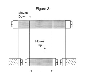
By building a somewhat more complex dual or compound flexural system, this dip can be compensated for, even in systems with considerable travel. In the compound system there are three platforms and two sets of flexures, one attached to the bottom of the other. When the first system dips down, the second system moves up and restores the output to a relatively straight line. See Figure #3.
In a compound system the input is made to the lower of the two moving platforms and the output is taken off the same platform.
Crossed Rotary Flexures
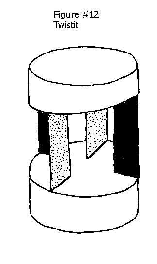
This off axis load problem can be corrected by using the somewhat more complex design of crossed flexures. In this design each of several sets of flexures are placed at right angles to the other so that they will present an absolutely stiff resistance to any right angle deflection. This stiffness is limited only by the physical properties of the flexure or reed material and its dimensions. See Figure #12. The only real problem with this arrangement is the difficulty of imparting the actuation force to the system without introducing parasitic bending. The activated platform of this system is moving in both a linear and a rotary path in relation to the actuating force. (see highly accurate flexural systems).
Disk or Diaphragm Flexures
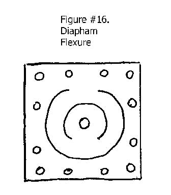
Disk or diaphragm flexures are a very unique form of linear flexures. A disk or diaphragm flexure system would consist of two flexural elements that are separated by a parallel body. The actuated part of the mechanism is on the central axis of the flexures. Although there are a variety of configurations that have been used, the two concentric but opposing “C” shaped cutouts are simple, very symmetrical and produce a very linear excursion of the actuated element. See figure #16.
Disk or diaphragm flexures can be used to provide selected stiffness in different directions by tailoring the cross section of the flexural elements. See figure #17
Efficiency
Giving an efficiency rating to a given flexure design will vary dramatically depending on the end use. If the operation is a near static situation, like the precise positioning of a gaging device, few of the excellent properties of flexures will be at a critical level. If on the other hand, the flexure is the coupling device for a voice coil or piezoelectric driven device operating at kilohertz frequencies, then even the smallest error source will be of paramount importance.
Without making any reference to the application, faithfully reproducing every detail of the input actuation, at all frequencies, with an accuracy down to the angstrom level, without adding any parasitic movements and having an infinite life expectancy are the parameters for a 100% efficient flexure. Machining the flexures as an integral part of the overall structure in a monolithic design will be considered close to 100% of the potential efficiency achievable.
A system consisting of brazed on flexures would be considered 90% efficient. The brazed flexure is, however, both difficult and expensive to produce. The problem here is centered around the difficulties of achieving the desirable metallurgical properties of the flexural member after brazing. A system that is seldom extolled is the clamped and glued design. By using a gluing system that consists of a high stiffness ceramic-filled epoxy, (see our literature) the efficiency may be as high as 80%. This glue will be almost as stiff as the platforms and physical contact with the reeds will approach 100%. All excess glue should be removed to prevent sharp ridges that will cause stress risers that will bring on early fatigue and catastrophic failure.
If the mounting bosses and the flexures are machined from a common block of material, with multiple tie down holes, the efficiency may be in the range of 55% and can be improved by gluing the joints. Using a simple reed held on by multiple screws behind a back up plate would be in the 45% efficiency range. A simple reed held in place by single screws, behind a backup plate will be in the range of 35% efficient. A simple reed held in place by screws behind a washer may be only 25% efficient. A simple reed held in place by a screw only, may be in the 15% efficiency range.
These numbers are highly empirical values that are based on experience in the field, but they coincide very well with other practitioner's experiences. If anything, they error on the higher side of efficiency. The efficiency can be either higher, or lower, depending on the quality of shop practice in manufacturing the mating parts.
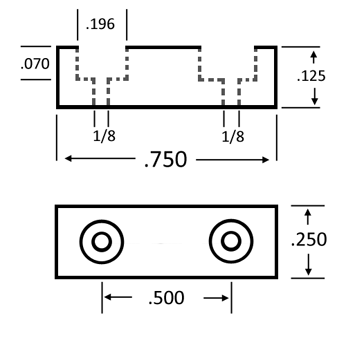
The surfaces of the platforms that actually contact the flexural reeds should be very well machined. The backup plate should be quite rugged in both width and thickness. The surface of the backup plate that contacts the reeds should be flat lapped for maximum compliance. Sizeable radii should be provided on both the backup plate and the platforms adjacent to their contact with the reeds. This will avoid stress risers that can contribute to fatigue failure of the reeds.
Faults
When assembling individual component parts to produce the flexural system, it is often the case that only a small percentage of the reed that forms the flexural element is actually in metallurgical contact with the platforms. The dilemma of clamping the assembly together is the number one problem for reed type flexural designs. These clamping problems manifest themselves as backlash, hysteresis or micro-slip and can even cause fretting in extreme cases.
Some of the other faults that can occur with flexures are load induced, columnar buckling, it is difficult for flexures to cope with shear loads and there may be parasitic bending of the reeds, caused by off axis application of the actuation force, or coupling to the load. There can also be catastrophic fatigue failure after long periods of use.
Helical Motion Flexures
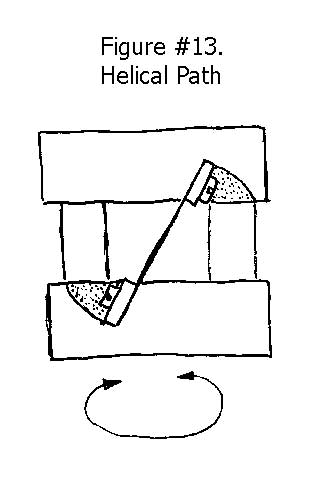
“Duck” is a simple, clever, design that provides both a linear and a rotary motion to the payload. It provides a more subtle linear motion with a much longer range than the conventional disk or diaphragm design. This configuration uses three or more reeds mounted at an angle to the platform faces. The movable platform will actually depict a helical path that is defined mainly by the inclined angle of the flexures.
This design provides a much studier construction when you have plenty of axial space but are limited in radial real estate. It also uses standard inexpensive reed flexures and backup plates; instead of requiring expensive, uniquely designed and built disk flexures and backup plates. See Figure #13
Highly Accurate Flexural Systems
For the ultimate in accuracy there are a couple of fine points that should be considered. The activating force, should be applied, at a point on the center line between the two platforms and the reeds both vertically and horizontally. See Figure #7.
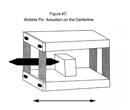
The activating force should be applied through a buffer mechanism. This will minimize any parasitic movements i.e. (Twisting and bending of the reeds).
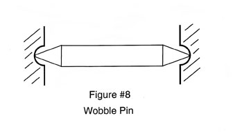
The wobble pin is the simplest form of buffer mechanism. The wobble pin should have small spherical radii on each end, that rest against, or butt up against a slightly larger spherical radii in the driver and the driven cups. The wobble pin is supposed to wobble, to perfect the alignment between driver and the driven. The wobble pin should be relatively long as it is the ratio of its length to the radius of the small contact radii, that determine its efficiency, in attenuating dynamic misalignment between the driver and the driven. See Figure #8.
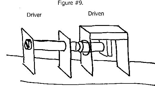
A driven flexure system that in turn drives the input end of the “functional” flexure through a spherical contact, against a flat surface is another viable but less efficient approach. See Figure #9.
Material
The material for our standard offthe shelf flexures is blue tempered and polished spring steel, as previously discussed. Custom flexures can be constructed using materials with unique physical, corrosive resistant, magnetic, or electrical properties on special order. Custom Flexures can also be constructed from materials with special high or low temperature performance characteristics.
Multiplication and Division
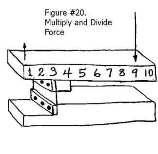
You can multiply a force by dividing it. By building a simple lever with a flexural hinge as the fulcrum, very accurate multiplication or division of the applied force or the length of movement can be achieved. It’s obviously not something for nothing, because in multiplying the force, you divide the movement and vice-versa, see Figure #20. As with all flexural systems, the linear travel is limited as is the load carrying capacity for a given size.
Permanent Z Axis Adjustment
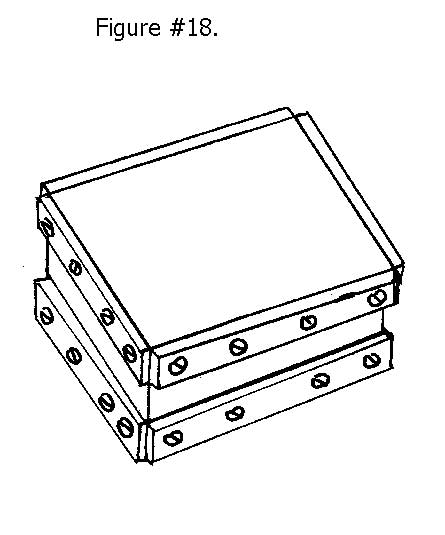
The extreme stiffness of a reed type flexure at right angles to its flexural axis can be used in an unusual way to adjust and fix the elevation and attitude of a payload. This is done by placing two sets of flexures at right angles to each other. The mounting holes are elongated or just made oversize, so that the exact elevation and the angular attitude of the upper platform can be adjusted to micro inches while the clamping screws are under slight tension. When the exact desired position is reached, all of the mounting screws are cinched up tight and the long term position of the payload is fixed. See Figure #18.
Pinch Clamp
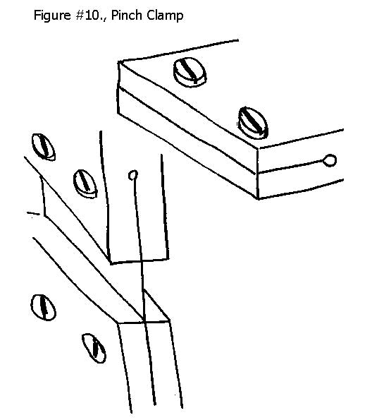
The pinch clamp can be a perfect solution for locating flexures for some applications. Its unique feature is that it is monolithic. This single piece construction provides 50% higher load carrying capacity, simply because both the body and the back up plate are a common part both of which share the load. This can be very important when heavy loads are involved, but especially when a hanging load such as a pendulum is the payload.
A hinged pinch clamp that is itself a flexure is produced by machining a precision slot with an end relief in the body of the device. The two wings of the flexural hinge are closed on the reed of the flexure with a threaded fastener or fasteners. The precision slot and the high clamping forces will yield close to 100% contact between both sides of the reed, that is the flexure and the clamping body. See Figure #10. Modern machining technology in the form of the wire E.D.M. (Electric Discharge Machine) can be used to produce an almost perfect geometry slot with a gap to match the thickness of the flexure.
Problems with Flexures
So far the discussion of flexures has been all positive or at worst there were simple fixes for their shortcomings, but there are two inherent problems that can, at best, be mollified. The very thin sections of material with very large surface area that make up the flexible part of the flexural system are subject to the almost instantaneous influence of temperature and the vibration sensitivity of flexural systems extends down below one half a hertz. You can limit the thermal reaction by keeping the flexural section as short as possible. The vibration sensitivity can be reduced somewhat by coating or attaching a high hysteresis rubber to the flexures. This rubber will also act as an insulator to slow down the temperature response time. We have already discussed the installation of stiffening plates, that will positively influence these factors.
Really Small Flexures
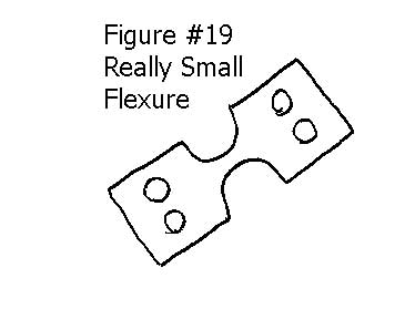
Very very small flexural hinges are difficult, if not impossible, to physically mount in the complex systems where they are needed. The simple solution is to manufacturer the flexures with large convenient mounting surfaces that neck down to the very petite area that form the flexural hinge. See Figure #19.
Restoring Force
Flexures are thought of as springs, but we should not make the mistake of depending on the flexures themselves to provide the restoring force, causing the system to return to the position of origin. Coil springs of either the tension or compression type are the most frequently used devices for this purpose. Dead weight applied through a cable or through a bell crank defiantly has its place in providing the restoring force; but these mechanisms are more complex, and therefore more expensive.
Simple Reed Flexures
A high quality flexural platform might consist of two plates with two sets of two parallel reeds or flexures, (four reeds) see Figure #1.
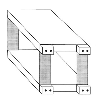
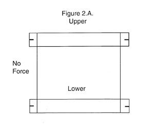
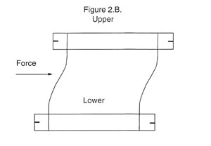
The upper platform is very flexible in one axis and is extremely stiff in a direction at right angles to that. If relatively long flexures or reeds are used, and the movable plate is displaced a considerable distance, the reeds will bend into an “S” configuration and the elevation of the un tethered platform will dip slightly. See Figure #2. Basically all of the bending will occur adjacent to the points where the reeds are connected. To minimize the dipping, keep the flexures or reeds as short as practical and limit the travel of the platform to a necessary minimum.
Simple Rotary Motion Flexures
A single long narrow reed with the bending area held quite short will depict a fairly accurate radius. Our catalog version of this flexure is three quarters of an inch (19mm) wide by one and a half inch (38.1mm) long and has ten holes for secure mounting. See our flexures part#FX-LN-75-1.5 with backup plate #BP-LN-75-1.5 Table B, See Figure #11.
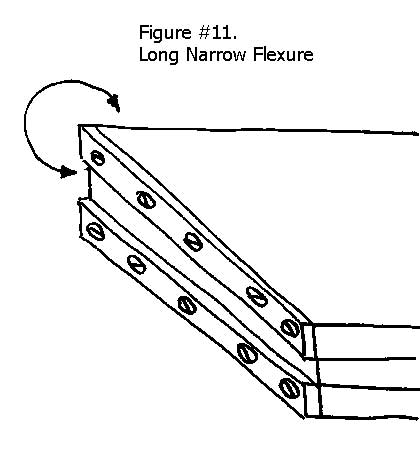
The weakness of this design is that any off axis load, applied to the reed, by the driver or the driven devices, will deflect the platform out of position and cause a distortion of the radius produced.
Sophisticated Flexures
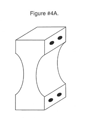
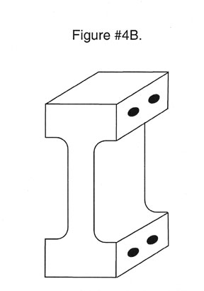
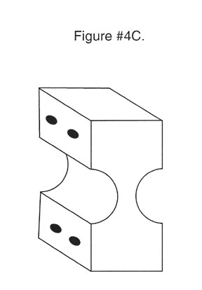
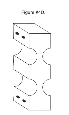
Much more sophisticated single flexure designs are available that provide superior performance compared with the basic leaf spring configuration. Using these designs, it is easy to double the columnar buckling load while maintaining the same flexibility. These monolithic structures, in effect, combine the flexural reed and the backup plate into a single more rigid element that can be much more efficiently mounted.
Single flexures can be produced with cross sections that are straight, tapered, or that conform to one curve or another. These cross sections can depict the radius of a circle, a parabolic, an ellipse or it can be hyperbolic. See Figure #4. A.B.C.D.
Monolithical Flexural System
An entire Multi-Flexural system can be produced as a monolith, by machining the entire system from a single block of material, using sophisticated computer controlled, wire E.D.M. machines. See Figure #5
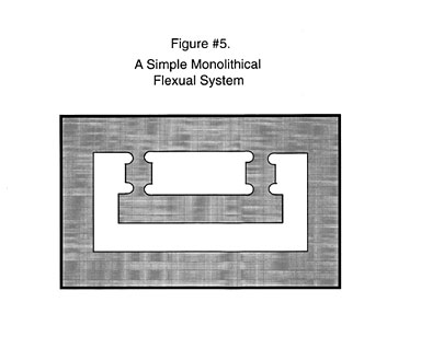
At the present time, we are only building sophisticated flexures and monolithic systems on special order. Standardized production of more sophisticated designs will be undertaken when users indicate their satisfaction with the merits of some given configurations.
Stiffening Plates
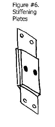
Dramatic increases in the columnar buckling, load carrying capacity, of a flexure can be achieved without any sacrifice in the accurate travel of a linear flexure by simply attaching stiffening plates to the center section of the reeds. See Figure #6. This improvement in stiffness and load carrying capacity can be had without any loss in performance. This occurs due to the obvious increase in structural mass and the fact that all of the former bending of the reeds, will still occur near the attachment points and none in the central portion of the reed. The stiffening plates achieve two more substantial benefits. Adding thermal mass to the very thin reeds dramatically increases the thermal response time of the system. This will in effect delay the almost instant dimensional reaction, to changes in temperature of the very thin reed, with such a large surface area for heat exchange. The second is that the resonate frequency of the flexural system is driven way up by the addition of stiffening plates.
Twist it
Another flexural system that provides almost pure rotary motion is known as twist it. It consists of three or more in line reeds between two platforms. This array of radial reeds is perfectly stiff (limited only by the physical properties of the component parts), in the plane at right to the flexures, but will rotate freely around the axis of the flexural bundle (see figure #12). As one of the platforms is rotated, the distance between them will dip slightly, just as simple flexures do. If this slight linear movement is a serious problem, it could be isolated from the driven mechanism by a flexural coupling or possibly by a bellows. It would be somewhat complicated, but a compound flexural system could be built that would automatically compensate for this slight dip. See also wire and cylindrical flexures for rotary motion.
Very Small Flexures
There are times when a very small flexural hinge is required. >For these situations our tiny one quarter of an inch (6.3mm) wide by three quarters of an inch (19.05mm) long, Part Number FX-25-75 series, may provide the answer. This very small flexure uses our standard one quarter inch (6.35mm) by one quarter inch (6.35mm), backup plate, Part Number BP-25. With one backup plate at each end you are left with a one quarter inch (6.35mm) wide by one quarter inch (6.35mm) long flexural hinge.
This is the smallest, standard, off the shelf, flexure that we offer. If these very small devices are still too large for your application, we can custom manufacture flexures and backup plates to your exact specifications.
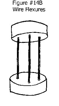
Wires and Cylinders as Flexures
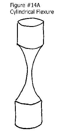
A cylindrical form provides uniform flexibility in a 360-degree plane at right angles to its cylindrical axis. They will also allow rotation around the “Z” axis in the form of Yaw. At the same time it gives almost zero deflection in the plane that is in line with the cylindrical axis. These flexures generally consist of wires, or cylinders machined into an hourglass configuration. See Figure #14. The cylindrical flexure is a special case application, but when needed they can solve some difficult problems.
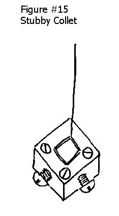
One of the main limitations to the practical implementation of cylindrical wire flexures is the difficulty of attachment. Glue can’t take the high stresses. Welding or brazing is expensive and seriously disturbs the metallurgical properties of the flexures. The solution is to hold the wire in a stubby collet attaching device. In addition to firm mechanical constraint, it allows universal adjustment to accommodate any length of wire flexure. The same stubby collar design will accommodate a wide range of different wire diameters (See Figure #15).
Another associated application for wires or cylinders is to provide a single degree of constraint to a mechanical system. A degree of mechanical freedom can be constrained by a wire held in tension just as accurately as if a sphere were in physical contact with a surface. The same stubby collect attaching devices used with wire flexures, can be used in this application also.
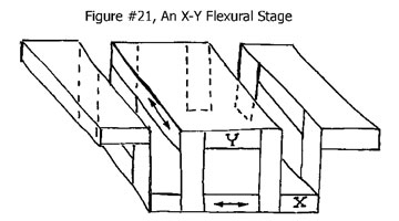
X-Y Stages
A simple X-Y stage consists of two separate sets of flexures set at right angles to each other. Each axis is actuated by a separate device to achieve two axis positioning to the desired location. A simple conceptual model is shown in Figure #21.
Position compensating, compound flexural designs, can be constructed that will produce very accurate right angle movements over a limited range.
The Wobble Pin
Isolating the driver from the driven in a one-degree of freedom system presents a challenge. In an ideal situation, the driving force will be on a centerline that passes through the center of gravity of the system’s mass. Figure #1. A sphere against a flat plate is a good approach; but any off axis translations can resolve into distortions of the truly straight-line of motion for the drive.
A secondary carriage that is driven and in turn drives will give the required buffer, or a simple wobble pin can be used. By providing a non-influencing outlet for off axis forces, so that they do not result in distortion of the straight-line motion of the driven carriage, the desired result can be achieved. Figure #2. The wobble pin is typically a relatively long slender rod, with a high quality spherical radius on each end. These spherical radii are coupled to the driver and the driven systems through a pair of three constraint couples. These couples can be a conical cup for low performance systems, a three ball couple for high performance systems at low load, to a trihedral clamp for high performance high load systems. All of these kinematic devices are discussed in detail in other parts of this paper.
In low load systems the wobble pin is an effective way of decoupling a rotation, if the driving mechanism from a non-rotating driven element. It is often reported that the wobble pin can only be used in compression, but the fundamental concept can be applied in tension as well. By using a sphere that is larger in diameter than the cylindrical diameter of the Wobble Pin, the three constraint coupling can be placed on the back sides of these two spheres and the off axis correcting mechanism will work in tension. Figure #3. A wire constrained at both ends is technically a flexure. However, it will fulfill the essence of the wobble pin’s function when used in tension.