Bal-tec™ Home Length Standard Ball Bar Used to Calibrate Machinery
Length Standard Ball Bar Used to Calibrate Machinery
Although there are verbal reports that Mr. Hickey of General Dynamics in San Diego, California used Ball Bars to evaluate the performance of giant milling machines in 1940, the first patent for a Ball Bar was issued much later to the Lawrence Livermore National Laboratory in California.
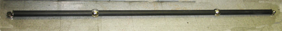
The original concept of the Ball Bar was for the volumetric evaluation of machine tools. One of the advantages of this procedure is that knowledge of the actual length of the Ball Bar is not required. Another unique advantage of the Ball Bar is that there is no practical limit, to the length that Ball Bars can be constructed. Two and one half meter long (2.5 m, 8.2 feet ) Ball Bars are common for Laser Tracker and Optical Scanner calibration.
A volumetric evaluation of a C.M.M. consists of measuring the length of a Ball Bar in a number of different orientations and locations, within the machines’ envelop. A volumetric evaluation will not only provide a picture of the overall machine performance, it will identify each and every one of the parametric error sources involved.
Typical of man’s nature, soon after the N.B.S. (now N.I.S.T.) introduction of the Ball Bar as a Standard Reference Method ( S.R.M. ) for Coordinate Measuring Machine ( C.M.M. ) calibration; users started trying to use the Ball Bar as a length standard.
From the very beginning of the attempts to make the Ball Bar a length standard, large disparities in the measured length of Ball Bars surfaced. Even the calibrations by different international standards labs varied considerably. When measuring the length of a Ball Bar with a coordinate measuring machine, what the machine actually sees is the ball center to ball center dimension.
In contrast, the vast majority of Ball Bar calibration procedures use a single axis machine to measure the overall length of the Ball Bar. Previously, the more or less random variations in the measured length of Ball Bars were charged off as random errors of unknown origins. With more measuring experience, these dimensional variations were traced to systematic errors with a well defined cause.
Why are there such calibration problems? When a Ball Bar is used for volumetric evaluation, a slight bending of the Ball Bar won’t have any effect, on its performance. If you bend a Ball Bar that is used as an archival standard even slightly, the true inter ball length of the Ball Bar will be changed substantially. As more use is being made of the Ball Bar as a length standard, new realities are coming to light. One of the most perplexing phonemes in using the Ball Bar as a length standard is the “Camber Effect.”
Over the years little attention had been paid to this problem, because it has no effect on the results when the Ball Bar is used for volumetric evaluation. For volumetric evaluation, the Ball Bar is mounted one time in a “clamp” or in a “cradle,” and it is left installed for the duration of the evaluation. The “Camber Effect” starts with at least a slight bend in the shaft of the Ball Bar. At first glance you might say, “so what.” The result of this bend or camber of a Ball Bar is a resulting “change” in length of a bent ball bar as it is rotated in the field of earth’s gravity, and as it is moved from vertical to horizontal. The results of the “Camber Effect” on the measured length of a Ball Bar are far more subtle, than a small change in the length of a Ball Bar due to its orientation in the earth’s gravitational field.
If the bend or camber of the Ball Bar is placed up in relation to the earth’s gravitational field when it is measured, the length of the Ball Bar will increase. If the same bent Ball Bar is measured with the bend facing down the length of that Ball Bar will actually measure shorter. If the bent Ball Bar is measured as it is rotated, the length will depict a sinusoidal change in length. The two main variables that change “Camber Effect,” are the length of the Ball Bar and the magnitude of the bend or camber.
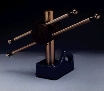
We have built a test bench to dynamically demonstrate this real world variation in the measured length of a Ball Bar. A standard one meter long ( 3.28 feet ) Ball Bar with only a small bend, will exhibit several microns of change in length when it is rotated 360 degrees. No one ever seems to factor the human element into the calibration equation. In the assembly and calibration room of a large C.M.M. manufacturer, a technician was performing a Ball Bar evaluation on a completed C.M.M. machine. He dropped the Ball Bar on the machine table. One of the balls sheared off the Ball Bar, bounced across the table, dropped to the floor and rolled half way across the room. The technician picked up the ball and dusted it off on his shirt. He walked over to his tool box and got out a tube of Krazy Glue ®. He applied a drop of the glue and stuck the loose ball back on the Ball Bar. He then resumed the calibration procedure.
As bad as this sounds, outside of a tiny flat or two, it would have little or no effect on a volumetric evaluation, but it would have been a total disaster if the length of the Ball Bar were being used as a length standard.
If the Ball Bar is to be used as a length standard for the calibration of a Coordinate Measuring Machine, here are several strong suggestions to make:
- The length of the Ball Bar must be calibrated frequently.
- The Ball Bar should be kinematically supported out toward the ends
- The same kinematic support system should be used during the calibration operation as when the Ball Bar is in use.
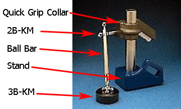
- The rotational position of the Ball Bar in the Kinematic coupling must be maintained during both calibration and use. The rotational position of the Ball Bar is typically clocked with a kinematic couple. This usually consists of two precision cylinders that are crossed at 90 degrees and are magnetically preloaded.
All of the hardware for this application can be purchased off the shelf, or the component parts can be purchased to build the assemblies to fit your needs. (See Ball Bar clocking in our web catalog).
Any deviation from these procedures will result in substantial errors, in the measured length of the Ball Bar. The ideal design to use for a length calibrated Ball Bar, is our “Cantilever” series. This design uses two auxiliary support balls way out on the end of the Ball Bar.
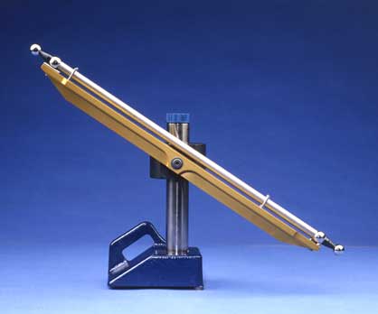
This “Cantilever” Ball Bar is supported by the appropriate “Way Out Ball Bar Support Rail.” [See these products in our web catalog] Our line of standard tubular Ball Bars offers mild steel shafts that have a thermal coefficient of expansion of 6.4 micro inches per inch per degree Fahrenheit ( 6.4 X 10E-6 in/in °F) and tubular shafts of Invar® (a metal alloy) which has almost no expansion or contraction with changes in temperature.
For Ball Bars that are to be used as the ultimate length standards, when calibrating the most precise of all Coordinate Measuring Machines, our Ultra Precise Ball Bars are available. The features of this series of Ball Bars include solid shafts for the maximum rigidity. These Ball Bars are made of an exotic alloy metal that is exposed to an exotic thermal cycle which results in a product that has long term dimensional stability that has not varied one micro inch per meter in 15 years.
The balls used on these Ball Bars, are selected grade 2.5, matched balls, that have been three cycles cold stabilized to provide the best long term dimensional stability possible. The shafts of these Ball Bars are precision ground to eliminate the “Camber Effect.”
How is the Ball Bar Calibrated for length?
Typically the diameter of both balls is measured first. This task sounds much simpler that it turns out to be. The forces applied to the surfaces of the ball by the measuring machine will cause four separate Hertzian elastic deformations that must be corrected for. The flat parallel anvils of the measuring machine will each be elastically dimpled at the contact points that touch the ball. Each side of the ball will be flattened by contact with the faces of the flat parallel measuring machine anvils under the measuring force.
The mathematical calculations required to compensate for these four elastic deformations are quite complex. The value for the variable required for these calculations are:
- the force applied by the measuring machine
- the stiffness or Young’s modulus of elasticity for the measuring machine anvils and for the ball itself
- the value of the Poisson’s ratio of the ball material and that for the measuring machine anvils Poisson’s ratio is the so called barrel effect. It is the ratio of the on axis or in line strain to the bulging or cross axis strain. If you put a load on the top of a barrel, how much shorter would it become in contrast to how much fatter it would become. Strain, in this case is a change in shape of the test part caused by the stress or force applied to it.
One of the most accurate and by far the least risky methods of calibrating the exact diameter of the Ball Bar spheres is to compare their diameter with the diameter of a NIST traceable master ball. The significant advantages of this technique are that, all of the elastic deformation are nullified and it eliminates any temperature uncertainties. The long linear measuring machines usually used to measure Ball Bar length are typically huge lumps of cast iron or granite. Large machines such as these may require an entire week of time to equilibrate. Make sure that the machine has been at 68° Fahrenheit ( 20º Celsius ) night and day for a good long time before attempting to use it.
Ball Bars are typically quite long, so the temperature of the Ball Bar and of the surrounding environment is critical. A standard steel Ball Bar has a thermal coefficient of expansion and contraction of 6.4 micro inches per inch per degree Fahrenheit. ( 6.4 × 10E-6 in/in °F) If the absolute temperature of the measuring lab varies 2 degrees Fahrenheit, a one meter long ball bar will change length 6.4 micro inches times 40 inches equals 256 micro inches per degree times 2 degrees equals 512 micro inches or about one half of a thousandths of an inch.
Another key factor is the measuring machine used to make the primary calibration. A recent controversy was resolved when it was found that the scale of an older linear measuring machine was using the old surveying inch instead of the modern “International Inch.” On a one meter Ball Bar this amounted to a deviation of almost one ten thousandth of an inch.
In another case, the company was using a dream machine. They had a Moore Measuring machine with a laser interferometer, but they were supporting the Ball Bar in a kinematic coupling that located on the master balls themselves; and they were getting a couple of microns variations in their measurements due to the “Camber Effect.”
How flat and parallel are the measuring machine anvils? Measure the diameter of a good quality, one quarter inch diameter ball ( ¼”, 0.25”, 6.35 mm ), in five places. Measure the ball diameter in the center of the anvils, at the rear, at the front, at the top and at the bottom. All readings should obviously be exactly the same. If all readings are not exactly the same the anvils must be re-lapped. It will take a good, skilled technician about six hours to properly recondition a set of anvils within one or two micro inches.
What is the total error budget or uncertainty of the measuring machine? How is the N.I.S.T. traceability achieved? The final dilemma is the same one that was faced with all four of the Hertzian elastic deformations of the two ball surfaces, and the two anvils’ surfaces, when the diameter of the balls was determined. There is a serious misnomer regarding the effect of the measuring force on the compressibility of the Ball Bar shaft. Basically you can just forget it! This is the one thing that isn’t working against you while using the Ball Bar as a length standard. A four ounce ( 4 oz, 113.4 gr ) measuring force placed on a one meter long ball bar will only compress the length of the bar about two tenths of one micro inch ( 0.0000002”, 0.00000508 mm )