Bal-tec™ Home The C.M.M. Evaluation Primer
The C.M.M. Evaluation Primer
The ball bar
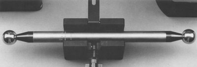
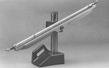
A Ball Bar consists of two very round spheres of exactly the same diameter securely attached to the opposite ends of a rather long rigid bar (see Fig. #1.). The center to center distance between the two spheres is absolutely constant. This means that no matter where the Ball Bar is positioned within the Coordinate Measuring Machine envelope it should measure exactly the same length.
In reality what is measured is the sphere center to sphere center dimension. This distance should measure exactly the same because the intersphere dimension of a Ball Bar is the length of an infinitely small center of one sphere to that of the other. For this reason, there are absolutely no chances for any of the alignment or cosine errors that are so common to all flat parallel artifacts such as gage blocks, end standards and step gages.
Installing the ball bar
Most Ball Bars are rather long so they are very sensitive to the heat transmitted through hand contact by the calibration technician. Any hand contact should be limited to a very minimum and the technician should wear gloves to slow down heat transfer. After any hand contact, a thirty minute soaking period should be allowed for the Ball Bar to achieve thermal equilibrium with the C.M.M. environment, before any serious measurements are made. In the early days, elaborate multilayered insulation of the bar was provided. We have since found that this insulation so disturbs the thermal equilibrium pattern of the Ball Bar that it actually
The Ball Bars and their positioning device should be kept stored in the temperature controlled C.M.M. room; or they should be moved into the room the night before their anticipated use.
Traceable evaluation
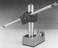
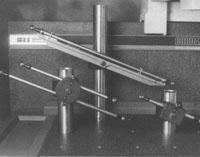
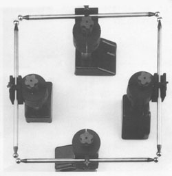
All of our Ball Bar clamping devices are designed to be very quick acting, so that only a brief hand contact is required when loading them; and no contact is required when changing the angle, the position, or the elevation of the Ball Bar. To install a Ball Bar in the free standing Ball Bar clamping device, first loosen the cap screw and set the clamp horizontal with the Vee-Block up. Next tighten the cap screw to secure the clamping device. Now loosen the four spoke locking knob and flip the clamping bar back. Quickly place the Ball Bar in the Vee-Block and flip the clamping bar forward, then tighten the four spoke locking knob (see Fig. # 2.).
Volumetric Evaluation
When an uncalibrated Ball Bar with an unknown sphere center to sphere center dimension is used in multiple positions to evaluate the performance of a C.M.M., that test is referred to as a "Volumetric Evaluation". The result of this evaluation is simply the shortest measurement subtracted from the longest measurement.
When a Ball Bar with an exactly calibrated sphere center to sphere center dimension is used, the evaluation is considered a "Traceable Evaluation" and the Ball Bar is referred to as an Archival Standard or Artifact. For this class of evaluation, the Ball Bar must be given special support in very rigid Kinematic devices. These devices are discussed later.
In addition to being an extremely cost effective evaluation device, the Ball Bar has a subtle but very important superiority over non-contact optical devices such as lasers and autocolimators. When using a Ball Bar, the contact force of the measuring probe is applied in exactly the same manner as when measuring an actual test part. For this reason the considerable elastic deflections of the machine elements will be factored directly into the data derived.
Diagnostic verses volumetric evaluation
There are 20 basic Ball Bar positions used for the Volumetric Evaluation of a Coordinate Measuring Machine. A table of these positions is given in the ANSI B89.4.1-1997 specification, "Methods for Performance Evaluation of Coordinate Measuring Machines". For a copy, write to ANSI customer service, 11 West 42nd Street New York, NY 10036 or telephone (212) 642-4900.
The Volumetric accuracy of the machine is derived by subtracting the shortest Ball Bar measurement from the longest, but of course, nothing is this simple! If there are measurement outliers, they must be remeasured to confirm or to correct them. If the aspect ratio of the machine axii are not one to one, then additional Ball Bar positions must be added and some positions must be overlapped, so there may be thirty or even thirty five Ball Bar positions required.
For making a Volumetric Evaluation of a Coordinate Measuring Machine the technician blindly follows the Ball Bar patterns laid down by the ANSI specification. For Diagnostic Evaluation on the other hand, a systematic positioning of the Ball Bar to separate and quantify each one of the individual error sources is required.
Interpreting the errors
Understanding the meaning of variations in the measured length of Ball Bars in the different positions is much easier to comprehend than the output of complicated electro-optical devices. The Coordinate Measuring Machine is one extremely complex system. When using the Ball Bar to evaluate specific parametric errors, it must be realized that serious discrepancies in one area of the machine may affect the evaluation of another basic perimeter. If, for instance, the temperature sensor on one of the axii scales is not functioning or is malfunctioning, it will reflect in the Ball Bar length reported for positions using that scale. If the Ball Bar is used as a frequent interim check rather than just for a once a year calibration, you have a decided advantage in identifying the error source. If the machine was functioning properly and then something goes wrong, only that one error source needs to be isolated.
If one axis is out of square with another, it will cause a difference in the measured length of an inclined Ball Bar when measured in 180 degree reversed positions. To evaluate the squareness of the Z axis to X and Y, the Ball Bar is vertically inclined at about 45 degrees and measured while held at a 90 degree angle to the axis to be evaluated. Then it is reversed 180 degrees and measured again (see Fig. # 3.).
For evaluating the squareness of the X axis to the Y axis, the Ball Bar is measured while set horizontal at about 45 degrees and then reversed 180 degrees and measured again (see Fig. # 4.).
One way of visualizing how this works is to think of the angle at which the Ball Bar is inclined as going with the squareness error of the machine in one direction so that it will measure shorter than it actually is. While the squareness error of the machine will go against the angle of the Ball Bar when it is reversed 180 degrees, the Ball Bar will measure longer than it actually is.
To measure the rotational errors around and along the X and Y axii, the Ball Bar is inclined at a vertical angle of about 45 degrees and placed at 90 degrees to the axis of interest, then it is measured in several locations from one end of the axis to the other (see Fig. #5.). To obtain the maximum sensitivity the test probe should be oriented horizontal and at 90 degrees to the test axis.
The Z axis roll or rotation is an error that has long been overlooked. When using vertical measuring probes this error is of very little or no importance. With the advent of horizontally oriented measuring probes, this condition has taken on great significance.
Scale evaluation
Using a calibrated Archival Ball Bar for evaluating scale accuracy is the best approach, but these calibrated artifacts are not in wide use. Using an uncalibrated Ball Bar to check the accuracy of the scales requires the use of some logic. This logic is based on the results of checking the Ball Bar length parallel to each one of the three axii. If all three measurements are the same the probability is very high that the scales are all performing well. If on the other hand one scale or all three scales are giving different readings it is obvious that there is a scale problem. Prior to evaluating the scales all squareness and roll errors should have been corrected for, as they can effect this evaluation in some fairly complex ways.
For evaluating the "Z" axis scale, the Ball Bar is set straight up vertically. The vertical Ball Bar is usually measured in two positions in each of two diagonal corners at the extremes of the machine envelope (see Fig. # 7.).
For evaluating the "X" axis scale, the Ball Bar is set horizontal and placed parallel to the long axis. It is usually measured twice, once near the table top at one edge of the envelope and then across the table at the top of the travel (see Fig. # 8.).
For evaluating the "Y" axis, the procedure is the same as for the "X" axis, but rotated 90 degrees (see Fig. # 9.).
Ball bar support
Because the dimensions usually associated with Ball Bars are quite long, they must be supported by a very rigid device to avoid bending and twisting motions. The support bodies supplied by Bal-tec™ have four general forms.
The free standing ball bar on the heavy duty stand
The Free Standing Ball Bar is the simplest and the most widely used technique. In this approach the Ball Bar is simply clamped near its center to the post of a very rigid vertical stand. A robust vertical post is a prerequisite to avoid the serious errors due to torquing of flimsy ordinary indicator stand designs.
This stand has a heavy structural base with a large rigid 2 inch (5. l cm) diameter vertical post. There is a strong clamping mechanism that is used to firmly attach the Ball Bar to this vertical post (see Fig. #10.).
The Heavy Duty Stand has three rather large diameter hard stainless steel feet that are precision lapped flat and coplanar. This Kinematic design provides the most mechanically stable platform possible for the size involved (see Fig. #11.). The Heavy Duty Stand is manufactured in three standard heights of 14 inches (35.6 cm) (Part# FS -14), 24 inches (61 cm) (Part # FS -24) and 36 inches (91 cm) (Part# FS -36). Just setting the Heavy Duty Stand on the Coordinate Measuring Machine table usually makes it stable enough to locate the Ball Bar for measurement.
Clamping down the heavy duty stand
When the situation requires it (for very long Ball Bars or for machines using a "hard probe"), the position of the stand can be rigidly fixed to the table of the machine. To do this, we supply a long screw that passes down through the center of the large two inch (5.1 cm) diameter vertical post and is securely screwed into one end of an aluminum cylinder. The other end of this cylinder has an M10 x 1.5 threaded hole that will accept our "Dual Threaded Adaptor Screws" ( see Technical Data Sheet C.M.M.- 14, Table #1.). The proper adaptor screw will thread into one of the tie down holes in the C.M.M. table. On machines with a Tee slotted table, it can be screwed into a Tee-Nut. A Blue Five Lobbed hand tightened knob (Part # 80010) is used at the top of the two inch post to rigidly fix the position of the stand on the table (see Fig. #12.).
The abalone vacuum chuck
The second is the Abalone, a 5 inch (13. cm) diameter, high vacuum chuck that will secure the Anchor to granite and other refined surfaces with almost 290 pounds of hold down force (see Fig.#17.).
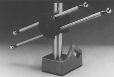
The way out ball bar support
This device is a very rigid Tee shaped aluminum rail that Kinematically supports the Ball Bar. This added support virtually eliminates any bending of the Ball Bar. In use, The Way Out Ball Bar Support is attached to either a single mount collar or a Tri-mount collar on the Heavy Duty Stand or the Anchor. A socket head shoulder bolt passing through the center of the aluminum rail is used to secure the device to the collar. The desired angle is set and the Way Out Support is clamped down. The next step is to place the Ball Bar in the Kinematic mounts of the Way Out Support. The Kinematic mount on one end of the rail consists of three precision lapped, hardened stainless steel balls. They are arranged in a circle to form a nest that holds one of the Ball Bar support spheres. The Kinematic mount on the other end consists of two precision lapped, hardened stainless steel cylinders. They are arranged parallel to the rail and form a cradle that holds the second Ball Bar support sphere. The Ball Bar is pulled into the Kinematic mounts by two rare earth magnets.The Way Out Ball Barsupport is strongly recommended for use on Ball Bars over 600 mm (24 inches) long. This type of support is absolutely required when using any length of calibrated Ball Bar for a traceable evaluation. All Way Out Ball Bar Support mechanisms are interchangeable with any Ball Bar clamp and will fit the collar on any vintage of Heavy Duty Stand or Anchor (see Fig.#18.).
For Interim C.M.M. Checking — For the Monday Morning Check of C.M.M.'s — The Indexing Ball Bar Support Devices
The third form of Ball Bar support bodies are the rotating support devices most often used for fast interim or Monday morning evaluation of C.M.M.s.
A magnetic hold down for the heavy duty stand
On cast iron and steel tables that are without any connecting mechanisms, the stand can be held in place by the powerful rare earth magnet (Part # FS-MAG). This magnet takes the place of the aluminum cylinder (see Fig. #13.). The final clamping of the stand to the table is accomplished by hand tightening the Blue Five Lobbed Knob (Part # 80010) at the top of the 2 inch (5.1 cm) diameter post.
The Dual Thread Adaptor Screws
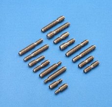
Because there has been a wide assortment of thread sizes used on different C.M.M. tables over the years, an array of "Dual Thread Adaptor Screws" are available to match any table thread size to our standard M10 x 1.5 tie down screw, (see Technical Data Sheet C.M.M.-14 Table #1,. for a list and part numbers of the standard sizes available.) We also maintain an inventory of pre-threaded blanks that we will custom tailor to any unusual thread size you may need (see Fig. #14.).
The anchor as a free standing ball bar holder
The Anchor is the second form of support body for holding free standing Ball Bars during evaluation. It is a very effective device that has been well tested in the field. It consists of a three inch (7.6 cm) diameter steel tube that is precision ground and hard surfaced. It is held rigidly in position on the C.M.M. table through a threaded adaptor screw that locates in the lower bulkhead of the Anchor.
This device is manufactured in four standard heights of 4 inches (10.0 cm) (Part # AN-4) used only as an extension, 8 inches (20.3 cm) (Part # AN-8), 12 inches (30.5 cm) (Part # AN- 12) and 24 inches (61 cm) (Part # AN-24). The Anchor has three distinct advantages over the Heavy Duty Stand. It is much lighter in weight than the stand and the 8 inch (20.3 cm) version is low enough to use on very small measuring machines. Using the various lengths of Anchors screwed together in different combinations, there is no post left standing above the Ball Bar to cause an accidental wreck with the measuring probe. The light weight is a real advantage when the device must be carried all over the country on an airplane.
The very good rigidity of the Anchor is comparable to that of the Heavy Duty Stand. Because the Anchor will not stand alone and must be screwed down to the C.M.M. table through threaded tie down holes, every time it is moved, it is a lot slower to use than the Heavy Duty Stand. In addition, it must be positioned directly over a tie down hole in the C.M.M. table, so it is somewhat less versatile than the Heavy Duty Stand (see Fig. #15.).
The 4 inch magnetic platform
There are two alternative methods of fastening the Anchor down to the C.M.M. table. The first is a special 4 inch (10.0 cm) diameter magnetic base (see Technical Data Sheet C.N.C.-2.) that will clamp the Anchor down to cast iron and steel tables (see Fig.#16.).
Ball Bar Bending
For those who are well acquainted with the science of precision measurement, a bending moment of the Ball Bar is obviously a second order or cosine error and should be of relatively small consequence. In this case, the bending has a subtle and insidiously serious effect. When the contact force of the measuring probe is applied to the surfaces of the spheres, the resulting bending of the bar will vary dramatically depending on the angular position of the hit. There will be substantial bending perpendicular to the axis of the Ball Bar and absolutely no bending on the very end. When the computer tries to rationalize the input data due to this bending, it sees two much smaller diameter spheres. Because there is no bending at the very ends, the center distance between the two smaller diameter spheres appears to be much further apart.
The cantilever ball bar
The most advanced Ball Bars are of the Cantilever design. They are usually produced to the ultra precise quality and are frequently calibrated as archival artifacts. With this arrangement, there are two additional spheres mounted just behind the master spheres that are used for mounting purposes only. In use, these two auxiliary spheres are held in Kinematic couplings that support the Ball Bar and prevent any bending. In addition to supporting the Ball Bar, this design leaves the complete master sphere available for measurement. This design is entirely compatible with all Way Out Ball Bar Support. (see Fig. #19.).
The Two Ball Kinematic Mount
The Two Ball Kinematic mount or coupling, consists of two 1 inch (25.4 mm) diameter precision, hardened, stainless steel balls. They are spaced apart by a powerful rare earth magnet. This magnetic spacer makes each of the balls a powerful magnetic source of the opposite pole. When the precision lapped cylindrical diameter of the Ultra Precision Ball Bar is cradled between these magnetic balls an extremely rigid, totally self-aligning device is produced. The Two Ball Kinematic mount comes in a number of different mounting designs that all have the same function (see Fig. #23.).
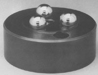
The Table Mounted Three Ball Kinematic Platform
The Three Ball Kinematic Platform is used to locate the lower end of the Ultra Precise Ball Bar. It locates directly on the C.M.M. table to provide extremely rigid support for the Ball Bar. In addition to providing excellent support for the Ball Bar, this device eliminates one half of the measurements that must normally be made. The lower sphere of the Ball Bar will remain in exactly the same position, no matter how many movements the upper end goes through, so it only has to be measured the first time. The Standard Three Ball Kinematic Platform will also attach to the top of any height Anchor so that one end of the Ultra Precision Ball Bar can be elevated to any height. This will facilitate meeting all of the A.N.S.I. Ball Bar positions (see Fig. #24.).
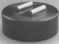
The two cylinder kinematic platform
The Two Cylinder Kinematic Platform is used with the Three Ball Kinematic Platform to hold the Ultra Precise Ball Bar for horizontal evaluations. This Standard Two Cylinder Kinematic Platform will also attach to the top of any height Anchor so that one end of the Ultra Precision Ball Bar can be elevated to any height (see Fig. #25.).
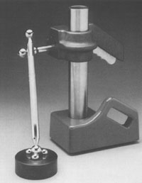
The quick grip stand
The Quick Grip Stand can be used to hold a Two Ball Kinematic coupling. With this two ball coupling mounted on a Heavy Duty Stand and a three ball coupling mounted on the C.M.M. table, a fast super accurate evaluation of the C.M.M. can be made. The elevation of the Ultra Precise Ball Bar, up and down, is facilitated by movements of the Quick Grip Stand on the two inch diameter post. Positioning the Ball Bar in different locations is achieved by sliding the Heavy Duty Stand over the C.M.M. table using the built in handle on the back side of the stand's base (see Fig. #27.).
A quick interim check - using the heavy duty stand or the anchor
A quick interim or Monday morning check of the C.M.M. can be made with as few as four positions of a Ball Bar or Ball Bars.The ball bar kit
A take off on the single Ball Bar for interim evaluation is The Ball Bar Kit where a special double Ball Bar clamping device (Part # FS-2BB) is substituted for the standard single bar clamp. The two Ball Bars are usually one short and one long, typically 300mm (11.8 inches) and 600 mm (23.6 inches) or 600mm (23.6 inches) and 900 mm (35.4 inches) sphere center to center. The extra data points collected from the double Ball Bar device tend to show up short, wavy errors. The length of the Ball Bar or Ball Bars chosen for the interim check should be as long as possible but short enough to allow the holding device to be rotated on the C.M.M. table to form the four sides of a cube.
- Set the Ball Bar at an angle that is steep enough to use as much of the machines Z. axis (up & down) as possible (see Fig. #27A.). FORM A CUBE
- Place a Ball Bar inclined at about 45 degrees near the center of the machine travel and as close to the front edge as possible.
- After making six well distributed hits on each of the Ball Bar spheres, print out the distance between them.
- Now move the Ball Bar to a similar position on the back side of the table with the stand rotated 180 degrees. Then measure the Ball Bar again. Next, move the stand near the left hand end of the table and orient it so that the Ball Bar is at 90 degrees to the original position and remeasure it. The last step is to rotate the stand 180 degrees and position it near the right hand end of the table and measure it.
This four position test, gives the C.M.M. a good work-out and will detect most serious problems before they can cause a calamity (see Fig. #28.).
For a more thorough check, you can add two more positions. The first has the Ball Bar horizontally oriented at 45 degrees to the original cube. The last position is another 90 degree reversal that places the Ball Bar at 45 degrees to the opposite axis of the original cube.
This technique of crossing the Ball Bar as detailed will actually amplify some machine errors making them even easier to detect.
Tri-mount collar
The Tri-mount Collar is a device used to further speed up the evaluation of C.M.M.s. It is capable of holding as many as three Ball Bar clamps at the same time. Using three double Ball Bar clamps, the Tri-mount could potentially hold as many as six Ball Bars. With one Ball Bar held vertical, one held horizontal and one held at an angle, all of the twenty positions specified in the ANSI B89.4.1-1997 can be achieved and with no personal contact with the Ball Bars (see Fig. #29.).
Temperature
Ball Bars are typically quite long, which makes them very sensitive to temperature. If the Ball Bar has been handled by the C.M.M. calibration technician at all, it must be allowed to standardize to the temperature of the C.M.M. environment for at least thirty minutes before any meaningful measurement can be made.
The number of hits
If you read the many papers published about choosing the number of measuring probe contacts (or hits) required to define a feature, you will find there are actually two situations. The first applies when you are measuring a machined feature with substantial form errors and a relatively rough surface texture. The second applies when measuring a gage quality surface of almost perfect form that has a very fine microfinish. About 17 hits are required to get a reasonably good picture of a simple machined feature, but when the geometry of the feature is approaching perfection, six well placed hits can do the job.
This Probe Characterizing technique uses computer software and an extremely high quality spherical artifact of a well known diameter to calibrate the radius of the contact tip. It will characterize geometry errors of the measuring probe (probe lobbing), it will compensate for bending of the probe stem and a broad range of other elastic deflections or bending moments throughout the machine. The sphere is very rigidly fixed to the C.M.M. table for this test. In effect, the C.M.M.'s computer is told that it is measuring a perfect sphere of a specific diameter and that any departure from this ideal form should be corrected in all future measurements. Some C.M.M. software is written around a specific master sphere diameter while other software is open to selection by the user.
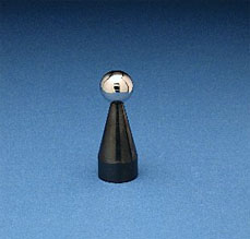
The most widely used sphere diameter is one inch (25.4mm) but 3/4 inch (19.05mm) is also widely used. In our experience down to about 10mm (.3937 inch) diameter, the smaller the master sphere used, the more accurately probe lobbing will be compensated for. This correction ends up being a simple adjustment in the apparent radius of the contact tip of the measuring probe (see Fig. #30.).
Repeatability test
This same spherical artifact makes an excellent Coordinate Measuring Machine repeatability test device. Its position on the table and its diameter are simply measured a considerable number of times (usually ten to twelve), and the results are compared. Each measurement consists of a small number of well distributed hits. Any variations in the measurements reflect a lack of machine repeatability. Valuable information about specific machine performance can be learned by looking at the end positions of individual axii. Note that this test must be performed as quickly as possible to avoid the influence of temperature drift.
A large percentage of repeatability errors are caused by a lack of rigidity in the C.M.M.s metrology frame. For this reason the repeatability errors in different X-Y locations and at different elevations above the table may vary significantly
Temperature drift test
An excellent test of the temperature drift effect on a C.M.M. can be made by fixing a characterization sphere in the very center of the measuring machine envelope. By measuring the size and position of the sphere at predetermined intervals over at least the normal period of machine use, but preferably over a twenty-four hour period, the machines temperature drift pattern can be evaluated. For an even more thorough temperature drift test, three of the characterization spheres can be fixed in a diagonal pattern with one in the center and the other two near the extreme corners. The three spheres should be elevated to three different levels above the tables using standard extension posts,(Part #P-EP-3 and Part #P-EP-6).
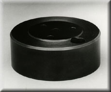
The 4 inch platform
To achieve the greatest mechanical stability and the most versatility, the Probe Characterizing Sphere is mounted on the 4 inch (10.16 cm) diameter platform (Part PLT-4). This platform is securely fastened to the C.M.M. table by a socket head cap screw with the proper thread to match the tie down hole in the C.M.M. table (see Fig. #31.).
The 45 degree block
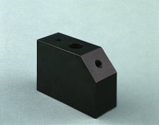
There is a 45 degree block (Part # BLK-45) available. The 45 degree block can be located in an out of the way spot on the table and the Probe Characterization Sphere can be extended well into the work area to allow for frequent validation (see Fig.#32.).