Bal-tec™ Home What is a Sphere?
What is a Sphere? How Are Spheres Made? How are Spheres Measured and How are They Used in Metrology?
The word sphere first appeared in the written English language in 1300. The early concept of a sphere was that of a radius being rotated 360 degrees around a line axis terminating in two poles.
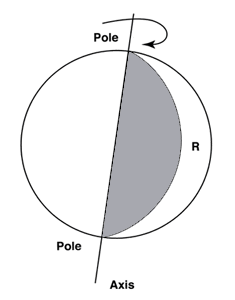
The modern technical definition of a sphere might be a three dimensional closed body with all points on its surface at an equal distance from a single central point. In a recent study that we did for the U. S. Air Force, each one of a set of test balls from 1/16 inch to 1 inch was measured at several different forces and the absolute size extrapolated to zero, see (Figure # 13.).
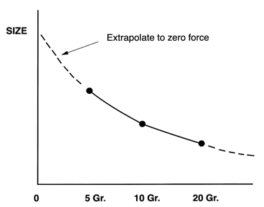
This study has reduced the uncertainty of the absolute ball diameter from maybe plus or minus ten microinches to probably plus or minus three microinches. Any finer measurement uncertainty than this is restricted by our uncertainty in the viscoelasticity of the surface due to its texture, metallurgy and as yet un-characterized molecular phenomena. The final results of this program were documented by an extensive calibration program done at N.I.S.T. using five color absolute interferometry and multiple force extrapolation to zero pressure.
Surface Texture
The quality of the surface texture of a high precision sphere is in the low microinch to nanometer range. The importance of the full spectrum of surface texture quality, for a mechanical component, is no where so manifest as for precision balls. Waviness which is often talked about but is seldom the major issue with other precision machined parts is of tantamount importance here. A Waveometer is a common measuring instrument in the ball metrology lab. It senses and reports the amplitude of undulations in the balls surface in several frequency bands. What makes this characteristic is so important in rolling element bearing applications is that its amplitude has such a dire effect on the vibration (noise) level of a running bearing. The Waveometer is a production test machine which requires a special setup for each size ball. In small lot production, we have had excellent results in detecting and controlling the waviness part of the surface texture by making full spectrum roundness measurements using a finely radiused stylus and low contact force.
Precise Measurement Techniques for Precision Balls
The metallurgy and chemistry of the materials that are often specified for precision balls is a major limiting factor in the quality of the surface texture that can be economically achieved on precision balls. The use of high chromium or tungsten in conjunction with high carbon content forms carbide particles in the body of the metal. The dramatic difference in the hardness of these carbide particles compared to the matrix or bulk of the material, causes them to protrude above, or out of the matrix, making it difficult and very expensive to achieve the highest quality surfaces. The high chrome and high carbon content is a major factor in the production costs of high quality 440c stainless steel balls that are so often used in metrology applications.
The micro finish of the precision ball surface is best measured by optical interferometry; although, commercial balls with Ra surface roughness levels of about two micro inches can be accurately evaluated with stylus type instruments. All interference measurements give a panoramic 3 dimensional evaluation, not the single line that is characteristic of stylus type instruments. Without turning this into a seminar on surface texture interferometry, there are three basic systems that can be used: The least sensitive is the straight two beam device which is functional down to 0.7 - 0.8 microinches Ra, see (Figure # 14.).
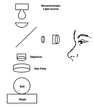
The next is the Tulanski type Multibeam micro Interferometer. Although this type system is capable of resolving less than one Nanometer steps, the eroded type surface texture generated by the balls rolling over the abrasive particles in the commercial ball lapping process limits this device to a resolution of about 0.1 microinch Ra, see (Figure #15.).
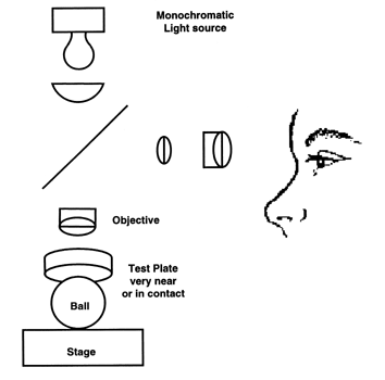
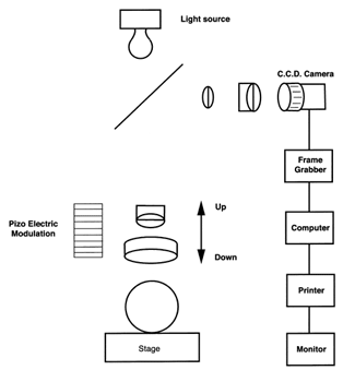
Interpretation of the interference patterns in the two beam and the multibeam systems is subjective, and requires a moderate amount of skill on the part of the technician. The most recent development is the phase shifting micro Interferometer, where some part of the optical system is modulated and data from the resulting interference pattern is gathered and analyzed electronically. The visual presentation of data by these devices is vivid and extremely valuable, but the mathematical manipulation of the spherical interference patterns tends to give Ra numbers that are in general a little bit lower than indicated by multibeam analysis. A key advantage of this equipment is that the data generated is objective and immediate and can be used for S. P. C. functions. The computer generated report can be transmitted electronically without having to use photographic techniques as with the prior two systems, see (Figure # 16.).
Variations in the common diameter within a group of precision balls are very important when they are used in rolling element bearings, because any variations in the ball diameters will cause vibration (noise), lower the load carrying capacity and shorter the life of the ball bearing. Extremely accurate common size evaluation is also important for some metrology applications such as Ball Bars, the spherical artifacts used for C.M.M. repeatability and temperature drift tests as well as sets of master balls used to standardize measuring machines throughout a company or an industry.
Determining the common size or rather the variation in common size of a group of precision balls can pose a serious dilemma. It is a forgone conclusion that no matter how round a ball is, it is not perfect so there will be some variation in the diameters measured at different locations on the ball's periphery. The Anti Friction Bearing Manufactures Association (A.F.B.M.A.) defines the variation in common size for a lot of balls as the average diameter of the smallest ball subtracted from the average diameter of the largest ball in the lot under test. This result can be quite different than that of subtracting the smallest measured diameter in the lot from the largest measured diameter in the lot.
Maintenance of Temperature Stability
There are special problems involved in accurately gaging the common size within a group of very precise balls. The number one problem is by far the maintenance of temperature stability during the period of measurement. This temperature stability becomes a much worse problem when measuring larger diameter balls. A temperature drift of 0.1 degrees Fahrenheit will cause a dimensional change of one micro inch in a 1.50 inch diameter steel ball. When you consider that the height of the gage stand is three or four times, then it is not difficult to appreciate the temperature problem. One of the things that we do to cope with the situation is to provide a well controlled environment. The frame of the gage is a gigantic gantry construction that provides a huge heat sink. In this way, the actual staging area is well shielded from any radiated energy and will be slow to move due to this physical mass. This gage is then surrounded by 5 inch thick blocks of aluminum that have serrated surfaces on all sides. The front access plate usually referred to as the breath shield is a solid serrated aluminum plate, as even inferred coated clear plastic would not stop the heat radiated by personnel in the area.
The serrations in the aluminum material used as heat sinks in the gaging area randomize any energy re-radiated from these aluminum blocks. The ultrasonically cleaned test balls are moved into the gage environment on thick aluminum soaking plates that are kept covered. They have been stored on wire frame racks for at least 24 hours to thermally normalize them before measurement. After removing the stainless steel cover, and closing the aluminum breath shield, the balls are moved by a plastic vacuum wand onto the kinematic gage anvil one by one for measurement. The three point contact of the kinematic gage anvil consists of two ring lapped tungsten carbide cylinders and the flat tungsten carbide face of an instrument micrometer, see (Figure # 17.). The two cylinders are rigidly clamped in parallel to form a self aligning cradle that will centralize the sphere to submicroinch accuracy. To make it even more complicated, the initial setting of the gage must be made with a master ball, as there is no other way to establish a zero using this kinematic anvil.
The final precaution, which greatly reduces the radiated body heat of the measuring lab technician from reaching the gaging area is that they wear an aluminized mylar poncho.
Ball Use in Metrology
A few of the calibration and metrology applications for precision balls include. The spindle evaluation of axis of rotation machine tools such as lathes, milling machines, grinders, and diamond turning machines. This can be done by measuring the periphery of an ultra high quality sphere attached to and rotating nearly concentric with the spindle under evaluation. The sphere is adjusted concentric with the spindle axis by four adjusting screws. By analyzing the resulting polar plot data, the real time performance of a spindle under actual operating conditions can be made.
A high quality master sphere can be used for the calibration and or compensation of those roundness measuring machines that are based on the axis of rotation principle. By indexing the angular position of this master sphere in relation to the measuring machine's spindle bearings, errors in the master sphere can be separated from spindle errors. Using this data, the spindle bearing errors can be characterized and compensated.
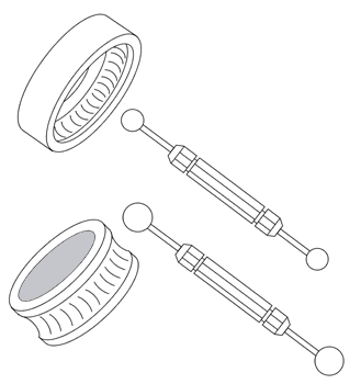
Balls are used as a go/no-go plug gages when large numbers of holes must be gaged. A ball plug gage is many times faster to use than a cylindrical plug gage, because it doesn't need to be lined up perpendicular to the test part surface in order to enter the hole. By applying a thin coating of prussian blue to the raceway of a ball bearing and drawing a ball across it, the ball radius to the bearing radius can be measured, see (Figure # 18.). Measuring the internal spherical diameter of rod end bearings is accomplished using two ball plug gages, each with two flats ground on the balls, see (Figure # 19.).
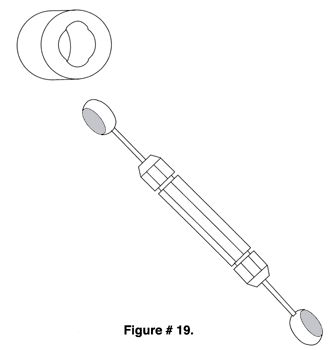
The dimensions of a gap between two surfaces can be measured by grinding a flat on the ball plug gage surface and inserting it into the gap. If the ball can be rotated it is smaller than the gap, if it won't rotate it is larger than the gap, see (Figure # 20.).
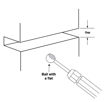
A ball gage unlike a cylindrical plug gage will enter an orifice at any angle so holes intersecting other surfaces at an angle can be evaluated with the ball gage, see (Figure #21.).
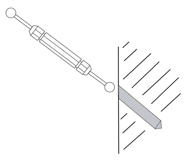
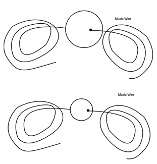
The inside diameter of pipe and tubing of any length can be measured by attaching music wire through center hole so that the ball can be pulled into the hole and then pulled back out if it won't go all the way through, see (Figure # 22.).
The C.M.M. Probe Characterization Sphere
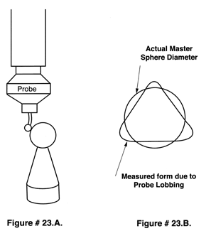
A very accurate sphere of well known diameter is used to establish the effective 3 Dimensional location of the probe tip center. The data derived from measuring this well known sphere is used by the C.M.M.'s computer to correct for asymmetric test probe lobbing, for all elastic deflections in the machines frame and for the bending of the probe tips shaft, see (Figure # 23. A. & B.).
The Ball Bar
The simple inexpensive Ball Bar can evaluate the overall performance of a Coordinate Measuring Machine or Machine Tool. The device consists of two almost perfect spheres of exactly the same size firmly attached to the opposite ends of a rather long rigid bar. The machine's performance can be evaluated by simply measuring the invariable length between the two sphere centers in a number of positions throughout the machines envelope.
Balls Used in Kinematic Coupling
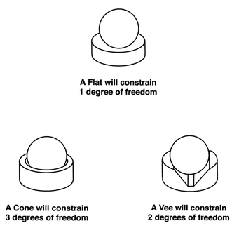
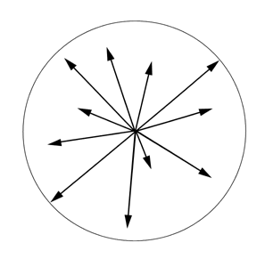
The classical Kinematic coupling consists of three spheres on one platform and a flat, a Vee, and a conical cup on the other. A physical body has 6 degrees of freedom. Kinematic couplings can be used to constrain any or all 6 of these degrees of freedom without distortion and with almost perfect repeatability, see (Figure # 24.).
How are Spheres made?
There are two basic techniques used for finishing precision Balls.
Spheres Generated by cup lapping.
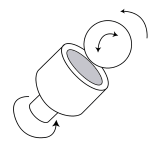
The cup lapping technique is similar to the method used to generate optical lenses. In this process a reasonably spherical blank ball is rubbed against the inside radius of a cup shaped tool with an abrasive slurry in between. There are many variations on this method, some using multiple cups, some using cups of varying shapes, but they all function on the same principle and they all have the limitation of only being able to grind a single ball at one time. Some very high quality balls have been produced by this method. Economically, the very nature of the process prohibits its use in commercial applications. As an old friend would say, "Even the Bank of England could never afford this product."
Commercial Ball Lapping
The centerless ball grinding method is the one used commercially. In this process a multitude of blank balls are fed between two annular ring shaped plates, of which one is rotating and the other is held static. The basic principle of this process is based on the gradual averaging of errors. Theoretically the three largest balls between the plates at any one time will receive the full load of the plates, and will therefore be quickly abraded. As the process goes on the variation in the size and in the roundness of the entire lot of balls decreases. One full load of balls produced on a commercial ball grinding machine varies from 500 to 1000 pounds. As you can see by the numbers involved, this is a very productive process.
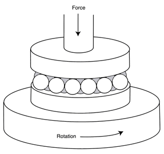
What quality of balls can be produced by the centerless grinding and lapping process? We recently produced an order of 64,000 pieces of high quality 3/16 inch (4.76mm) diameter balls, for one of the universities. A graduate student there spent four months measuring every single ball in this lot. His conclusion was that every single ball in the lot was round and the same diameter within less than three millionths of an inch, about .08 micrometers.
How are balls measured?
The level of precision required in the measurement of high quality balls is at the cutting edge of modern technology. The methods and the equipment used for these precision evaluations are adaptations of the standard measuring methods used for other fundamental geometries. Some of the important dimensional qualities of precision balls are their roundness or sphericity, their absolute diameter, the surface quality or surface texture, and the diameter variation within a specific group of balls. For pure convenience the roundness or sphericity of the geometric figure is usually determined by comparing its outside most surface with the Axis of rotation of a high quality spindle. The Axis of Rotation method of sphericity evaluation is simple but its accuracy is limited by the perfection of the cylindrical axis depicted by the rotating spindle.
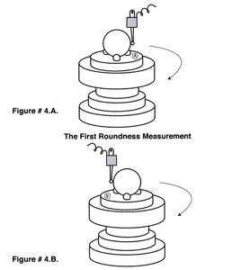
The errors of the spindle bearing can be characterized and factored out to a certain degree if a high quality master ball is measured and then rotated and re-measured. It stands to reason that the error in the master ball would move while the spindle errors would remain stationary. In practice the master ball is usually rotated 180 degrees and so is the measuring probe. By reversing both of the elements of the system we get a full manifestation of reversal technology so that the math required for the correction becomes very simple, see (Figure # 4. A. &B.).
Spindle Error Correction by Reversal Technology
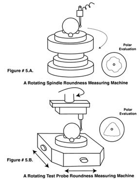
The configuration of these axis of rotation roundness measuring machines fall into two categories. In the first design the subject sphere to be evaluated is located on the rotating spindle itself, see (Figure # 5. A.). It is rotated concentric to the spindle axis while the relative displacement between the test part surface and the Axis of rotation of the spindle is measured and recorded, usually in polar form.
This machine design is economical and highly accurate but it is time consuming to use and is quite sensitive to temperature variations of the environment. The alternative design is to leave the subject sitting still while a test probe is rotated concentrically around it to measure and record relative changes in the position of its surface to that of the axis of rotation, see (Figure # 5. B.). This machine design is fast, accurate and quite insensitive to temperature variation, but the original cost of these machines is much higher than rotating spindle machines. This rotating probe design also has the advantage of being more amenable to vacuum holding systems. Having the test part static makes a vacuum system easy to install and use, see (Figure # 5. B.).
Sphericity
Sphericity is the most frequently disputed ball quality. Surprisingly the disagreements aren't due to the measuring equipment or to theoretical interpretation of roundness; but to problems caused by the method used to hold the ball for sphericity evaluation. Gluing the test ball to an auxiliary puck works very well, but it is slow and it is messy. In extreme cases the shrinkage of the glue can actually distort the ball. The best way to avoid this problem is to keep the glue line as thin as possible to use the smallest volume of glue feasible. A customer of ours caused 20 microinches (.5 micrometers) of distortion to a steel master sphere by using a center drilled hole to form the seat on which to glue down the 1.00 inch (25.4mm) diameter steel ball. This was caused by shrinkage of the large reservoir of glue under the ball.
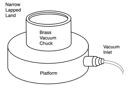
Magnetic chucks have been used with mixed results. It is extremely difficult to achieve a really round seat on a magnetic chuck so the balls will often wobble during evaluation, thus giving the appearance of a roundness error. For small balls, a vacuum chuck works well, however on rotating spindle machines they present a problem for connecting the vacuum source. The best configuration for a vacuum chuck is a brass cup with a very narrow lapped line of contact at the top. The break out diameter at the top of the cup should be about 1/3 of the ball diameter, see (Figure # 6.).
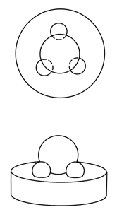
A three ball Kinematic chuck has no peer for holding balls during roundness evaluation, see (Figure # 7.). The one limitation to the use of the Kinematic chuck is that the mass of the ball must be adequate to hold it in position against the varying force applied by the changing position of the measuring probe.
Chuck Holding a Sphere
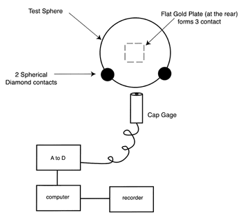
The sphere with its singularly unique geometric form offers us an alternative method for roundness evaluation. The origin of a sphere is an infinitely small point in space, and all points on its surface are by definition an equal distance from this point. That is its radius. This fact gives us the unusual ability to characterize its geometric form by using the outer surface as a reference datum. This geometric form is in distinct contrast with cylinders, cones and toroids. It is the only geometry who's position can be so perfectly defined with reference to a single set of cartesian coordinates, see (Figure # 8.).
The question is often raised as to how many points or circles must be measured to adequately evaluate a sphere. The answer to this question depends on what the application of the sphere is and how the sphere was generated. If the sphere is to be the rotating mass in a gyroscope that will be used in a satellite to study gravity waves the answer might be lots of measurements. On the Stanford University's Gravity Wave program they are measuring 17 longitudes and one equator. We have found that three orthogonal axii are adequate on high quality balls generated by the centerless method, however we often find local anomalies on the surface of commercially produced balls that are only 10-15% of the surface area. The peak errors in such small anomalous areas often don't show up in only 3 circles, see (Figure # 9.). It would be unusual however to only measure a single ball in a commercial evaluation so you become suspicious if you find even one low area in a lot.
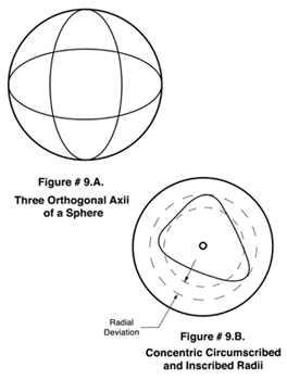
On our super spherometer we measure 64 points to form each of the 3 orthogonal circles that make up our spherical evaluation. When doing subjective evaluation of the polar chart recording of a roundness profile there are 5 common methods of evaluating the data. The best technique for spherical evaluation, that has good correlation with the actual vibration of a bearing as measured on an "Anderometer" is the derivation in the concentric Radii of two circles, one circumscribing the outside- most peaks and one interscribing the inner-most peaks, see (Figure # 9. B.).
The Absolute Diameter
There has been a fundamental change in the modern approach to making precision and ultra precision dimensional measurements. Previously comparative techniques were the norm. A stack of calibrated steel gage blocks were wrung up and used to set a comparator gage that was then used to measure the dimension of a steel test part, see (Figure # 10. A. & B.).
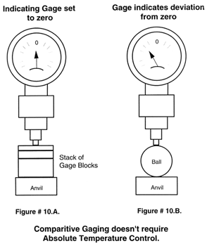
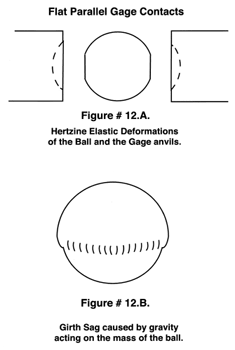
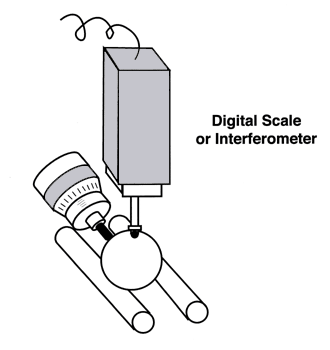
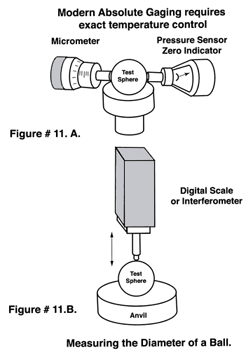
Temperature variations of plus or minus one or even two degrees were not a serious problem. With today's approach to making precision measurement using absolute devices such as digital scales and interferometers, which are orders of magnitude faster and more accurate than the comparative methods, but are also orders of magnitude more sensitive to absolute temperature, see (Figure # 11. A. & B.) Even the most minute deviation from the absolute standard temperature of 68 degrees Fahrenheit ( 20 degrees Celsius ) becomes an integral part of the new precision measurements. To compound this problem, the exact thermal coefficient of expansion of a test part is seldom known to an accuracy better than plus or minus 10%, which makes correcting for temperature more difficult. When making the precise measurement of ball's diameter, physical contact with the two opposing gaging surfaces is required. Any physical contact between the gaging surfaces and that of the ball will cause considerable Hertzian elastic deformation, see (Figure # 12. A.).There are mathematical formulas to correct for these deformations, but they are limited in accuracy mainly by the uncertainties in the Young's modulus of elasticity of the materials involved. This uncertainty is compounded by the fact that these values have been derived by tensile tests, while our measurement of size is made in compression.
It is quite obvious that there are two measuring surfaces and two spherical surfaces involved, so we have four elastically deformed surfaces to correct, see (Figure # 12. A.). On larger balls there is an additional problem that is derived from the force of gravity as it acts on the mass of the ball. This girth sag is something significant, for instance, according to NASA calculations a 10 inch (250.4mm) diameter stainless steel ball will have a 1.4 microinch sag so we are talking about almost 3 microinches (.07 micrometers) on diameter, see (Figure # 12. B.).
