Bal-tec™ Home Loosy Kinematic Coupling
Loosy
“Loosy” is a condition that results from a kinematic coupling design that is subjected to both contact elasticity and structural elasticity. “Loosy” is prevalent in dynamic systems that are in motion, particularly stop and reverse motion. It most often manifests itself as an error in one or more of the rotational degrees of freedom. It is hard to find black and white words to accurately describe this situation. Loosy is when you look at a kinematic design, and you have intuitive feelings that everything is not quite 100% perfect. All of the rules may have been satisfied, but you have this queasy feeling that this design is not the best approach.
There are designs, there are good designs, and then there are great designs. “Loosy” applies to areas where there really isn’t a great way to achieve the desired results, or at least the designer isn’t aware of the really good technique. One of the sacred cows contributing to “Loosy” designs is the frequent statement or instruction that “Kinematic components should have a low Young’s modulus of elasticity and a very high tensile strength”.
Tensile strength, or more correctly, the proportional limits of the materials involved are of paramount importance, but it is only seldom that they are the make or break condition of a Kinematic design. A larger radius of curvature for the spheres, with a better surface quality will raise the load carrying capacity by many orders of magnitude, while maintaining repeatability at an acceptable level. If the physical size of a larger sphere, is unacceptable, just use section of the sphere. (See The Rose Bud). What is needed to minimize “Loosy” in a given design is a slippery slope that will allow the component parts to slip over each other, properly positioning them; before the full load is applied and full elastic compliance sets in. The number one factor in achieving this is to use the stiffest component parts possible. This will mean that we use parts with the highest Young’s modulus of elasticity possible, not a low one.
For an order of magnitude guide line, see Table 1. for the stiffness of materials. Note that Aluminum has an Youngs Modulus ( Y.M.) 10 million P.S.I., while diamond averages 800 million P.S.I.
| Material | Young's Modulus ( Y.M.) Million P.S.I. |
|---|---|
| Aluminum | 10 |
| Cast Iron | 20 |
| 300 Series Stainless Steel | 20 |
| Steel | 30 |
| Ceramic | 45 |
| Tungsten Carbide | 100 |
| Diamond | 800 |
The mating of a good kinematic coupling is a thump, while a “Loosy” coupling is a squish. It is not crisp! When you increase the load on a “Loosy” coupling, there will be a movement in location that will far exceed the expected movement based on the elasticity and the geometry of the component parts involved.
Consider the general concept of slippery surfaces, with regard to “loosy” as a lack of repeatability. A curved surface such as a sphere or a cylinder will be more slipper than a flat surface with relatively the same contact angle. This is due to the simple fact that they offer less compliance. At the same time, nothing is free. The contact stresses between positive curved surfaces will be much higher than those for a plane surface, so the safe load carrying capacity will be lower.
Vertical Kinematics and the Aspect Ratio
Two of the areas that end up with “Loosy” kinematic coupling designs are vertical or off axis systems and systems with exaggerated aspect ratios The worst problems of all occur in systems where the payload is shifted from one angular attitude to another during use. In this situation, you expect some movement due to changing Hertzian elastic deformation, but in a “Loosy” situation there will also be considerable structural elasticity.
Keystone Coupling
A classic example of the “Loosy” syndrome is the Keystone Kinematic Coupling, described by Kittell in 1968. With this design, you are pulling the mating tongue of the Kinematic coupling into the vee of the keystone opening with serious force. To get good location and holding power, the included angle of the keystone opening will have to be quite steep at about 70 degrees. This steep angle will increase the structural elasticity compared with the more conventional 90 degrees. See Figure #1
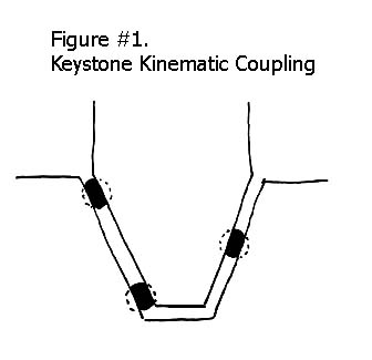
With the largest diameter balls that you can possibly use with female vees as the tongue, you will have extremely high Hertzian contact forces, with substantial stresses in the 70 degree opening. The balls will tend to be pulled ever deeper into the vees and the stresses will tend to pry open the 70 degree opening, even wider due to the required preload. This combination results in classic "Loosy”.
The keystone, sometimes referred to as the double vee, is by far the best design option for pick and place applications. So the task will be how to clean up the design to minimize “Loosy” not where to find an alternative approach.
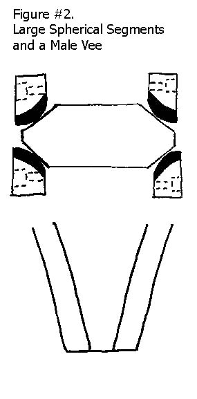
By using segments of a much larger sphere that is in the 4 inch ( 100mm ) diameter range, you grossly reduce elasticity. This approach is based on our “around the corner design”, (find under Kinematic Components). Using this approach, the Hertzian stresses can be lowered one hundred fold, and you still end up with excellent repeatability.
It is totally impractical to mate these larger spherical segments inside a female vee in the conventional vee block design, so we simply reverse the design and use male prismatic surfaces to form the tongue. See Figure #2
Nothing that we can do will eliminate Loosy in this design; but with these improvements, it will be so dramatically improved that it can be lived with.
Aspect Ratio
One of the other situations that will promote “Loosy,” is Kinematic couplings with exaggerated aspect ratios. It is ironic that exactly the same parameters needed to correct this dilemma with the Keystone coupling apply to this problem also. Stiff component parts with high quality surfaces and steep slippery interfaces with larger radius of curvature are required. With exaggerated aspect ratios, it is good to use the most powerful individual couples available. The three contacts of the trihedral cup is the most powerful Kinematic couple available, so we will use this at one end as a kind anchor or master pivot. Next, we will take a detour from conventional kinematic design by splitting the kinematic triangle in half. We put one couple at each end of the platform and one in the center.
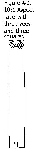
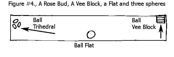
Some time ago, we developed a product that required a kinematic coupling with an aspect that was more than ten to one. Using three spheres and three vee blocks in the basic Maxwell kinematic design, with two vee blocks at one end and the third one at the other end, the part being supported wouldn’t even repeat within a thousandth of an inch (0.24mm). See Figure #3. After the redesign, it repeated as close as we could measure this thirty four inch long three inch wide part. It repeated better than five micro inches (125 nano meters). See Figure #4
Vertical Kinematics
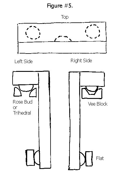
To cope with “Loosy” conditions in vertical and off axis kinematic couplings a fundamentally different approach must be taken. Some of the conventional arrangements of vee blocks and spheres work better than others, but they are all inherently “Loosy”. To cope with vertical kinematic “Loosy” is to alter the basic philosophy of the design. We will hang the platform from a powerful horizontal hinge, instead of the “Loosy” inclined vees.
A trihedral cup and a vee block are the most “powerful” kinematic couples at our disposal, so we will use them on top to form the hinge to hang the platform by. The third point in our vertical coupling will be the simplest of all kinematic couples, a sphere against a flat plate. Using this somewhat radical approach, we can turn one of the most difficult situations of “Loosy” into a rock solid structure, see figure #5.