Bal-tec™ Home Vee Block Design and Mounting Techniques for Kinematic Applications
Vee Block Design and Mounting Techniques for Kinematic Applications
Monolithic Vee Blocks
A monolithic kinematic vee block is the most widely used design. There are several variations possible. The included angle between the two plane prismatic surfaces can be varied to achieve a desired result. A 60 degree included angle of the prismatic faces will yield a 120 degree angle of contact with the ball. This angle will give the very best repeatability, but it will have very low load carrying capacity, due to the very high vector forces that result from this steep angle. (See Figure #1.) Any angle steeper than 60 degrees will start to cause wedging and sticking of the ball in the vee.
The most conventional design for a kinematic vee block is a 90 degree included angle. This angle will give good location accuracy, and reasonable load carrying capacity. ( See Figure #2 )
As the vees are flattened out further than 90 degrees, the load carrying capacity goes up rapidly, but the self centering or location accuracy falters. At about 110 degrees included angle, a limit for good repeatability is reached. (See Figure #3.)
Monolithic vee blocks are produced with two basic mounting designs. The surface mounted version has a flat back with two centralized threaded holes that go through the base at the intersection of the vees. This allows the vee blocks to be clamped down with two threaded fasteners from the rear. (See Figure #4.)
The second version of the monolithic vee block has a precision ground cylindrical post protruding from the perpendicular flat face of the precision ground flanged surface. There is a threaded hole going through the center of this cylindrical post, that allows this vee block to be held rigidly in place from the rear.
The front end of this through hole is counterbored so that this vee block can also be rigidly clamped down with a smaller diameter socket head cap screw from the front. This cylindrical post mounted device also lends itself to being press fit or shrink fit into the proper diameter hole in the platform. (See Figure #5.)
Split Vee Blocks
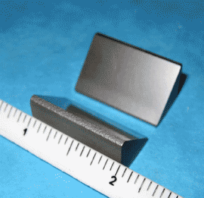
Another version of the plane prismatic vee block is the split design. In this case, the standard monolithic vee block is literally cut in half. These vee blocks end up as two rectangular substrata, usually with a 45 degree inclined face, that contacts the surface of the ball. This design has a distinct advantage over a monolith, in that the flat contact surfaces of these parts can be inexpensively flat lapped to achieve an exceptionally high quality surface finish and almost perfect geometry.
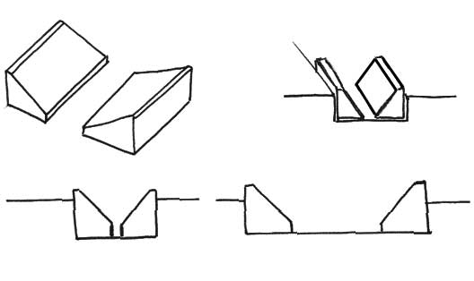
The simplest mounting method for the split version is to glue the component parts into a precise rectangular trench machined into the platform. The glue only needs to locate the split vees, as the bottom and side walls of the machined trench will take up the downward and outward forces. (See Figure #6.)
Cheating
I love to cheat the system a little, when I can get away with it! When you can break the laws of physics, or at least give them a good bend and walk way scott free, it is a warm sunny day. When coupling two bodies together, with a high degree of accuracy, three points of contact, or the “tripod rule” is a marvel, but in a rectilinear world, three equilateral points of contact, don’t match the rectangular parts. The problem gets even worse when the aspect ratio of the mounting platform, doesn’t lend itself to an equilateral three point, coupling design. By using a pseudo Maxwell kinematic system, that basically consists of two standard Vee Blocks and one split vee block with four mating spheres, you get a perfectly functional kinematic coupling, that has the much more stable, four legs of support.
We produce a broad line of standard off the shelf Vee Blocks and Vee Block like products. We also produce several unique, off the shelf, split vee blocks. The technical aspects of using the split kinematic technique have been published by Dr. Alex Slocum of M.I.T. as well as by our company (See the list of technical papers on our website http://www.precisionballs.com).
Prismatic Post
Still another approach is to use a plane prismatic post. These devices consist of a cylindrical diameter post with a plane flat surface truncated off, usually at a 45 degree angle. This design has the same advantage as the other split version in that the flat faces can be economically flat lapped to very high quality.
These parts can be located on the top surface of the kinematic platform with a threaded fastener, or even better, they can be glued and clamped on with a threaded fastener. Another version of the plane prismatic post, is somewhat longer than the surface mounted version. This device is mounted by gluing it into a close fitting cylindrical hole in the kinematic platform. The cylindrical post design, approach allows the same high surface quality and excellent geometry, as that of the other split kinematic design, and it is somewhat more compact. (See Figure #8.)
Cylindrical Vee Blocks or Cylindrivee™ Blocks
We will have to broaden our concept of the vee block for the next series of designs, referred to as CV Blocks or Cylindrivee™ blocks. High quality cylinders are relatively inexpensive to produce. By rigidly mounting two of these high quality cylinders parallel to each other, we can produce conditions similar to the flat prismatic faces, of a standard vee block. Using precision ground and lapped cylinders, there is less elastic compliance due to the smaller contact area between the parts, so the kinematic ball will find mechanical equilibrium more repeatably.
By adjusting the distance between the two cylinders, the contact angle with the ball can be set. The load carrying capacity of a kinematic coupling will be lower, when using cylinders, than it will be with flat surfaces, because the Hertzian loads will be so much higher. The smaller the diameter of the cylinder, the higher these Hertzian stresses will be. As a general concept, a smaller diameter cylinder will present a steeper slope to the mating ball, so with all other factors being the same, it will repeat more accurately.
Mounting the cylinders to form CV Blocks can be done in several ways. Two complete cylinders can be mounted by press fitting or shrink fitting the cylinders into the body of the platform. (See Figure #9.)
Two complete cylinders can be glued into a precision machined rectangular pocket in the top of the platform. (See Figure #10.) Two complete cylinders can be epoxy glued into precision cylindrical pockets machined in the platform with a ball milling cutter. (See Figure #11.)
The complete cylinders can have two blind holes drilled near each end and they can be glued into a cylindrical pocket over two pins. (See Figure #12.)
The two cylinders, that form a high quality vee block, can be held down, in two cylindrical recesses, with threaded fasteners, from behind. This is done by providing a threaded hole, in the cylindrical surfaces, near their ends. (See Figure #13.)
Truncated cylinders with a flat ground on them can be glued to the top surface of the kinematic platform. This method is very fragile, as the cylinders will pop off the platform with the slightest tap. (See Figure #14.)
A much stronger design is to machine a shallow recess into the platform surface and glue the flat side of the truncated cylinder into it. This will add greatly to the shear strength of this design. (See Figure #15.)
By drilling a blind hole, into the flat surface of the truncated cylinder, near each end and gluing the cylinder down over two pins, a really strong, but still economical, system is created. (See Figure #16.)
By far the most popular approach for mounting the two cylinders is to use the truncated version with two threaded holes near the ends. They are held in place by two threaded fasteners from behind. (See Figure #17.)
Larger cylinders, either complete or truncated, can be held down by using socket head cap screws passing through drilled and counterbored holes at each end of the cylinders. This method has the disadvantage of having the top of the counterbore exposed, that can cause damage of the mating balls in the other platform. (See Figure #18.)
One of the most unique approaches to generating CV Blocks, of the highest quality, with a much higher load carrying capacity, is to use sections of larger diameter cylinders to form the vee blocks. By taking a precision ground and lapped cylinder and splitting it into four equal sections, we produce the “Quarter-Round™”. The easiest way to mount the “Quarter-Round™” is to epoxy glue, two of them into a precision machined trench, in the kinematic platform. (See Figure #19.)
In situations of high vacuum or other specialized environments, which preclude the use of glue, a thread hole can be produced in the corner of the “Quarter-Round™” so that the parts can be mechanically clamped in place with a threaded fastener. (See Figure #20.)
By placing the threaded hole off center, the quarter round can be reversed after a period of use to expose a new contact surface to the mating ball.