Bal-tec™ Home Adjustable Kinematic Couplings
Heavy Duty Adjustable Kinematic Coupling
Making adjustments in the elevation, tip, or tilt of a kinematic platform has historically been a major problem without a good solution. The most common approach to adjusting changes in elevation was to mount a ball on the end of a fine-pitch threaded-shaft. The shaft and the ball rotate while the ball is in contact with the two faces of a mating vee-block. Rotating the threaded-shaft extended the ball, causing one corner of the kinematic platform to raise or lower depending on which direction the threaded shaft was rotated. But the very small area of contact of the ball with the flat surfaces of the vee-block resulted in extremely high Hertzian stresses.
The big problem with this design begins with the strong tendencies for these highly-stressed rotating surfaces to interact metallurgically with each other, causing spalling and then galling and ultimately fretting, with large craters developing from the rotation of the two parts against each other under load. Another problem with this design is that there is always going to be some clearance between the flanks of the male and female threads, leading to unreliable retention of the original position between the two kinematic platforms.
Still another major problem is that the axis of the ball and the axis of the thread will not be perfectly concentric, so the X and Y positions of the adjustable platform will be constantly changing their positions in complex patterns as the thread is rotated. Another approach to providing adjustability is to provide a long cylindrical tube with a very close fitting cylindrical shaft with a spherical end. This spherical end usually consists of a precision ball that is press-fit into a hole in the end of the shaft.
The entire accuracy of this device depends on the closeness of the fit between the inside and outside diameters of these two cylinders. If the fit is too close, they will cold weld and gall into an immovable structure. There must be lubricant between the two cylinders to keep them from galling. This lubrication-filled gap will slowly move around, shifting the X and Y axes of the upper platform. The adjustment up and down is usually made by a fine threaded member at the top of the assembly.
For this kind of device to work at all, the engagement of the internal and external cylinders must also be of a considerable length. By machining a key-way-like feature in one end it can be made so that it does not rotate as the adjustment is made, but again, there still must be clearance between the key and the key-way. What it comes down to is that this kind of design isn’t very good. It is much too long, it is expensive, there is stick and slip, and far too much backlash for any fine work, and the kinematic contact points are inexorably damaged by adjusting them.
The FlexaSphere Kinematic Coupling
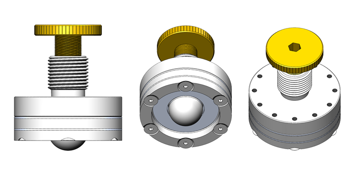
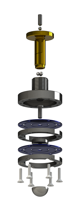
We have now developed a totally new approach to adjustable kinematic couplings called the FlexaSphere, which solves all of these historical problems that have plagued adjustable kinematic couplings once and for all. With this new design, the ball does not rotate! Our device uses a standard ball size of .750-inch. The ball material is a 58-HRC hardened stainless-steel.
The ball has no backlash at all and it does not drift over time. The basic design is a dual diaphragm assembly that is driven by a large .500-inch diameter 40-threads-per-inch male-screw mounted in an extremely rigid steel housing. The new design is totally free from any form of hysteresis! The assembly is so extremely stiff, it is hard to even compare it with any other style of adjustable kinematic coupling.
The ball moves straight up and down, so the adjustment causes no shift in the X or Y axes of the platform. This new approach to adjusting kinematic couplings allow easy movement in micro-inch increments for more than a tenth of an inch (0.100”) total travel.
Superior Position-Locking
There is a serious question that must be addressed in the design of all adjustable kinematic couples, that is: How do you lock the adjustment-screw in place after the final setting is made?
One option is not to lock the screw at all, but to depend on the fine pitch thread to remain where it was set. Using this approach, just a little vibration and your settings are lost. The most common locking mechanism is the jam nut. Using this method, there is a second nut that is somehow tightened against the end of the main body thread, stopping all rotation. A big problem here is that the clamping action always significantly alters the desired setting.
Another much better method is to split one end of the threaded-tube and tighten a tapered nut over it to compress the female thread against the adjustable male-threaded element, until it stops all rotation. This method is good, but it adds useless length to the overall dimensions of the assembly, it is bulky, it is expensive to produce, and it requires a high force to rotate the locking nut.
Our technique used on the FlexaSphere is to expand the outside-diameter of the male-threaded member against the female-threaded rigid housing. This locking method requires almost no torque. It locks all motion, making it impossible to move the setting. It does not change any of the settings, not even micro-inches. Finally, this clamping method is perpetual, there is no wear on any of the elements.
Flexacanoe: A Coupling for Higher Loads
An additional giant leap forward in kinematic design can be achieved by combining the adjustability of the FlexaSphere-750 in conjunction with our .750" Subminiature Canoe Sphere (CS-750-SM).
Because the FlexaSphere can produce precision linear movement without rotation, a canoe-sphere, capable of enormous load-carrying capacity compared to a ball, can be used instead, producing the FlexaCanoe.
Need Even More Load Capacity?
We are now producing a 4" diameter version called the Flexcanoe-2000, which uses our most popular canoesphere, the 2" diameter CS-2000-CPM in the same basic FlexaSphere design, allowing it to bear several thousand pounds. With the Flexcanoe-2000, our canoesphere can now be positioned in microinches at will.
| Part Number | Description | Contact Element | Drawing | CAD Model | Price |
|---|---|---|---|---|---|
| FlexaSphere-750 | 2" diameter with .750" Truncated ball | .750" Stainless Truncated Ball | Solidworks, IGES | $135 | |
| FlexCanoe-750 | 2" diameter with .750 Canoesphere | CS-750-SM Canoe | Solidworks, IGES | $392 | |
| FlexCanoe-2000 | 4" diameter with 2" Canoesphere | CS-2000-CPM | Solidworks, IGES | $405 |