Bal-tec™ Home All Ball Bar Information
All Ball Bars (Dumbbells)
Ball Bar (Dumbbell) Magic
Introduction to the Ball Bar (Dumbbell)
The Ball Bar (Dumbbell) is ultra precise and ultra simple, with the power to evaluate the performance of the entire Coordinate Measuring Machine System in just a matter of minutes. The first step is to understand the Ball Bar (Dumbbell) concept.
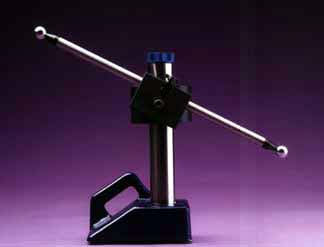
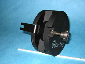
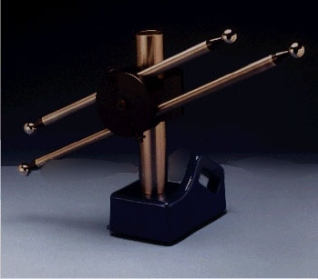
This tool consists of two ultra precise spheres of exactly the same diameters that are firmly attached to the opposite ends of a rather long rigid bar. The accuracy of the Ball Bar (Dumbbell) is only limited by the roundness of the two spheres and their common size. The ANSI-B89.4-1-1997 specification for "The Performance Evaluation of Coordinate Measuring Machines" requires that the quality of the Standard Ball Bar (Dumbbell) Spheres be round and common size within five millionths of an inch (.11 micrometers). The spheres for the Ultra Precise Series Ball Bar (Dumbbell) are held to two and one half microinches (.06 micrometers). For all practical purposes, these are the highest quality Ball Bars (Dumbbells) For proper evaluation, the Ball Bar (Dumbbell) must be held in a fixed position on the C. M. M. table by an extremely rigid Heavy Duty Stand (See Figure # 1.).
The function of the Ball Bar (Dumbbell) is so unique that it requires an open mind to really appreciate it. The center to center distance between the two spheres is absolutely fixed. A significant characteristic of the Ball Bar (Dumbbell) is that it has no cosine or alignment errors at all as contrasted with gage blocks. This is because the length of the line that defines the distance between the centers of the two spheres is represented by the distance between two infinitely small center points in space. When this tool is placed in various locations through out the envelope of the measuring machine, the sphere center to center distance should measure exactly the same. Any variation in the measurement of this distance indicates an error somewhere in the C. M. M. system.
This concept is referred to as a Volumetric check. The truly hard thing to accept is the fact that you are not even required to know the true center to center distance between the two spheres to effectively use the device. A knowledge of the exact sphere center to center gives the Ball Bar (Dumbbell) additional capabilities especially in evaluation of the scales.
Understanding the Implications of Various Deviations in the Ball Bar (Dumbbell) Length
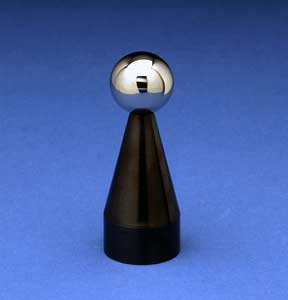
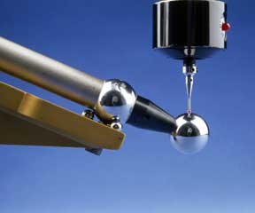
Strangely, the first step in the Ball Bar (Dumbbell) process does not involve the Ball Bar (Dumbbell) at all, but uses the probe characterization sphere instead. This first step is very important. The triggering characteristics of the probe head and the elastic deflections through out the machine caused by probe contact force must be compensated for (See Figure # 3.). Form errors in the contact tip must also be corrected for before any meaningful information can be derived from Ball Bar (Dumbbell) checks.
Before initiating the computerized probe characterization sequence, take a good look at the data derived from measuring the almost perfect characterization sphere. In most cases, the machine will report substantial deviations in both size and roundness of the master sphere. During the probe characterization sequence, the computer software will automatically compensate for roundness errors of the contact tip, elastic deflections throughout the machine and for lobing in the triggering mechanism of the measuring probe.
The real magic in Ball Bar (Dumbbell) evaluation comes from criss crossing the Ball Bar (Dumbbell). By measuring an angled Ball Bar (Dumbbell) placed right an angles to any axis of the C. M. M., and then simply rotating its position 180 degrees and measuring it again, the squareness of that axis can be critically evaluated. By moving the same angled Ball Bar (Dumbbell) to the other side or to the other end of the table and measuring it again, rotational errors around each axis can be determined.
For more iformation, please see theCMM Calibration Equipment Directory.
How to Choose the Right Ball Bar (Dumbbell) for your Application
Length
The first choice to be made is how long should the Ball Bar (Dumbbell) be? The length of the Ball Bar (Dumbbell) is defined at the distance from the center of one ball to the center of the other. As a general rule, the longer the Ball Bar (Dumbbell) is, the better it will exemplify the geometric errors of the machine. Having said this, a shorter Ball Bar (Dumbbell) will show up perturbations in the individual geometries better than a long bar. This phenomenon is a very sound reason for measuring multiple length Ball Bars (Dumbbells). Our Dual Ball Bar (Dumbbell) clamp (part # FS-2BB) is offered as a simple approach to solving this dilemma. This is accomplished by holding two parallel Ball Bars (Dumbbells) simultaneously. The advantages to this approach are much faster data acquisition and the elimination of temperature distortions, due to multiple handling of the Ball Bars (Dumbbells). A good rule of thumb is that the long Ball Bar (Dumbbell) should be about 80% of the length of the shortest axis of the measuring machine. The second Ball Bar (Dumbbell) should be one half of the length of the long bar.
Ball Size
The next parameters that must be decided are the size, the material, and the quality of the master spheres. A one inch 1.00" ( 25.4 mm) diameter master sphere is the industry standard, but three quarters inch 0.75" (19.05 mm) diameter and two inch 2.0" (50.8 mm) diameter, are sometimes specified.
Ball Material
The next decision is choosing the ball material. For touch fire or scanning C.M.M. probes that make physical contact with the subject, the standard ball material is a very high chromium, high carbon, Martensitic stainless-steel. This ultra fine-grained material is through hardened to 58 HRC (Hardness on the "C" scale) minimum and three cycle cold stabilized for long-term dimensional stability. This material has the same 6.4 microinches per inch per degree fahrenheit coefficient of thermal expansion as our steel Ball Bar (Dumbbell).
Ceramic or Tungsten Carbide master spheres can be supplied on special order. For optical sensing probes and photogrammetry applications: satin finished steel, titanium, or ceramic spheres are used. Satin finished white ceramic is the preferred material for most optical systems.
Ball Quality
The required quality of the master spheres is determined by the intended application. The standard high quality balls used for general commercial calibration are A.F.B.M.A.-grade five. This quality meets the requirements of the ANSI-B89.4.1-1997 Specification For Evaluating C.M.M. Performance. This is an instrument quality ball with a sphericity of five micro inches (127 mm). To meet this specification, both of the master spheres must be exactly the same diameter within five microinches (127 nm). The total surface texture of our grade 5 balls is held to less than 0.4 microinches (10 nm) Ra.
When calibrating high-end commercial machines and super accurate laboratory measuring machines, grade 2.5 master spheres are used. The required 2.5 microinch (63.5 nm) sphericity of these master spheres is right at the limit of commercial measuring ability. The total surface texture on these spheres, approaches 0.2 microinches (5nm). We have had many of these balls certified by international standards labs at less than one microinch (25 nm) sphericity.
On the satin finished ceramic balls, the rougher surface texture of the satin finish limits the quality of these balls to 25 microinches (635 nm). For use with optical probes this lesser quality is more than adequate.
Material For The Bar
The choice of material for the body of the Ball Bar (Dumbbell) is the next consideration. For calibrating, general-purpose commercial machines, the material generally used is annealed mild steel tubing. This material provides, a lightweight, stiff, structure that is the least expensive standard construction.
For longer Ball Bars (Dumbbells), or Ball Bars (Dumbbells) used in variable temperature environments all of our Ball Bar (Dumbbell) designs are available with Invar® tubular construction. The very low rate of thermal expansion of this material is its main advantage. In the room temperature range, this material simply doesn't grow or shrink any appreciable amount.
Long term dimensional stability of the bar is a special consideration for Ball Bars (Dumbbells) used to calibrate high end commercial or the ultra precise measuring machines used in standards labs. These Ball Bars (Dumbbells) are archival standards with the inter ball length calibrated to parts per million. This application requires a very exotic material, that is subjected to an exotic thermal treatment. The combination of material and thermal treatment yields a Ball Bar (Dumbbell) that has long-term dimensional stability, that has so far defied attempts to measure it.
Why not composite fiberglass or carbon composite? One simple word is hygroscopy. Water and water by products are produced by the curing of the plastic, so out gassing would cause the bar to shrink. If the humidity of the environment or contact with water liquid will cause it to grow, so you guess where it is at any given moment.
There is a way to automatically compensate the measuring machine for both the ambient temperature of the environment and the material being measured. This technique consists of using the C.M.M. to measure a laboratory calibrated Ball Bar (Dumbbell) made of the same material as the parts being measured, and to correct the measuring machine scales accordingly. If you are measuring large aluminum parts, you would use a long aluminum Ball Bar (Dumbbell) and likewise for titanium. Although this technique is not common practice in the U.S., it is widely used in some parts of the Orient.
Coupling The Ball Bar (Dumbbell)
Another parameter that must be decided is, how do we couple the Ball Bar (Dumbbell) to the support stand? For general-purpose calibration of commercial coordinate measuring machines, when the Ball Bar (Dumbbell) is less than 900 mm in length, the Ball Bar (Dumbbell) can be coupled on the Standard Heavy Duty stand or Anchor system using the standard Tri-Mount collar and any one of our Ball Bar (Dumbbell) Clamps. These include the standard Ball Bar (Dumbbell) Clamp (part number FS-1BB), the dual Ball Bar (Dumbbell) clamp (part number FS-2BB) for holding two Ball Bars (Dumbbells), the Short Ball Bar (Dumbbell) Clamp (Part number FS-1BB-S) or the Low Boy used to hold the Ball Bar (Dumbbell) way down at table height.
When the Ball Bar (Dumbbell) is 900 mm or longer, it needs a helping hand. This is achieved by using the cantilevered Ball Bar (Dumbbell) and the Way out Kinematic Ball Bar (Dumbbell) Support. When ultra precise laboratory machines are to be calibrated, the Archival Ball Bar (Dumbbell) is the artifact of choice. This device is always held by the Way out Kinematic Support System.
Ultra Precise Ball Bar (Dumbbell)
There is another Ball Bar (Dumbbell) holding system that is still used for laboratory class calibration. This is the Ultra Precise Ball Bar (Dumbbell) system (non archival). This is an accurate and reliable system that is the fastest approach to C.M.M. calibration, but it is very accident-prone. One careless move by the calibration technician and the Ball Bar (Dumbbell) will be pulled out of its Kinematic couplings and it will go bouncing across the C.M.M. table. Most companies now use the almost bullet proof cantilever Ball Bar (Dumbbell) and Way out Ball Bar (Dumbbell) Support to achieve matching quality, almost as quickly.
Very Short Ball Bar (Dumbbell)
Holding very short Ball Bars (Dumbbells) requires still another approach. There are two approaches to the very short Ball Bar (Dumbbell) holding problem. The first is to use our Mini Ball Bar (Dumbbell) and the second is to use the specialized "Hammer" Ball Bars. Both of these approaches work very well, but the mini Ball Bar (Dumbbell) requires its own stand while the "Hammer" can be used with any of our standard Ball Bar (Dumbbell) holding devices.
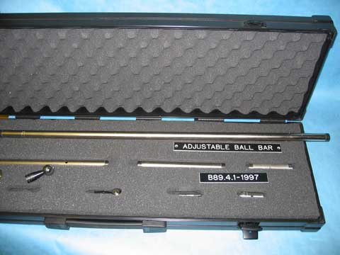
Adjustable Ball Bar (Dumbbell)
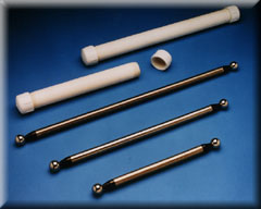
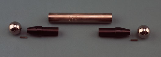
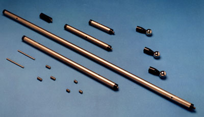
If you have a large number of very different size C.M.M.'s to calibrate, or if you are an outside contractor in the C.M.M. calibration business, you must consider the Adjustable Ball Bar (Dumbbell) Kit. This system consists of a number of different length tubular bars, with removable ends, which have the ball attached. Two of these spherical ends can be attached, one on each end of the tubular bar to form a Ball Bar (Dumbbell). A large number of different length Ball Bars can be created by attaching two or more different lengths of tubes together and then fixing a ball on each end.
Most adjustable Ball Bar (Dumbbell) Kits are ordered in Invar®. The temperature of the bar is raised when handling the adjustable Ball Bar (Dumbbell) to assemble it. By using Invar®, there is no growth from handling so the Ball Bar (Dumbbell) can be measured immediately after assembly.
Support Stand
The final choice is how to support the Ball Bar (Dumbbell) on the table of the measuring machine. By far the most popular support system is the heavy-duty stand. When holding long Ball Bars (Dumbbells) on big measuring machines the 36-inch tall Mammoth version of the Heavy Duty stand is the way to go. For calibration technicians who travel all over the country, the Heavy Duty Stand is just that, it is just too darn heavy. For these applications the very lightweight Anchor system is the answer.
The Anchor system has long suffered from the tedium of having to be tied down to the table directly over one of the threaded holes, then it must be removed and relocated and tied down again over another threaded hole. This pattern must be repeated many times during a calibration. The lightweight but mechanically stable 14" Trivet now eliminates this limitation. With the Trivet, the assembled Ball Bars (Dumbbells) can be zipped around the table as easily as if it were on the Heavy Duty Stand. The three legs of the Trivet form a large fourteen inch 14" (356 mm) diameter circle. This large footprint is used in order to achieve mechanical stability without the heavy weight.
The Standard Ball Bar (Dumbbell)
Standard Ball Bar (Dumbbell) for Evaluation of Coordinate Measuring Machines
- Accuracy
- The Ball Bar (Dumbbell) is the most accurate long gage device ever developed. The Ball Bar (Dumbbell) has no moving parts, it generates no heat, uses no magnetic fields and has absolutely no friction, stiction or hysteresis.
- Cost
- Ball Bar (Dumbbell)s cost only a small fraction of their more complex but far less accurate counterparts, such as long gage blocks.
- The Concept
- The concept of the Ball Bar (Dumbbell) is almost too simple. Two very round dimensionally-matched spheres are securely attached to opposite ends of a long rigid bar. The distance between these spheres remains constant regardless of the attitude of the bar. In the Free Standing Ball Bar (Dumbbell) system, the Ball Bar (Dumbbell) itself is clamped at its center to a rigid vertical post and the position of each of its two spheres is measured every time the position of the Ball Bar (Dumbbell) is changed.
The extremely fine-grained stainless-steel spheres used are 1.00 inch (25.4 mm) diameter. They are hardened to 58 HRC for long wear and ultra-cold cycled for long-term dimensional stability. They are held spherical within 5 microinches (127 nm) and both balls are exactly the same size within 5 microinches (127 nm). This meets the quality requirements for “Performance Evaluation of Coordinate Measuring Machines” ANSI / ASME-B89.4.1-1997. They are five times more accurate than high quality bearing balls. - Total System Evaluation
- In use, measurements of the distance between the two spheres are made with the Ball Bar (Dumbbell) positioned at various X-Y-Z locations throughout the C.M.M.'s volumetric capacity. From these data, the overall accuracy of the C.M.M. system may be determined. The C.M.M. system consists of the geometric or metrology frame, the test probe, the scale system, the computer and its software—plus the environment within which the system operates, including the temperature, vibration and the utilities. Because all of these elements are factored in by the Ball Bar (Dumbbell), it is a truly functional test of the entire C.M.M. system.
Using this approach, the test probe actually contacts the spheres. The system actually senses the probe trigger point, it records the scale position at that instant and then the computer calculates the true size and position of the spheres. Any errors of the C.M.M. system will cause erroneous readings or variations in the distance between the two spheres in the various positions. - Multiple Ball Bar (Dumbbell)s
- For ideal evaluation—and to help isolate errors—several lengths of Ball Bar (Dumbbell)s are desirable. The longest Ball Bar (Dumbbell) for a given calibration is usually 80% of the longest axis of the C.M.M. Because of sag, Standard Ball Bar (Dumbbell)s are seldom made over 39.37 inches (1000 mm) long. Giant Invar® Ball Bar (Dumbbell)s of composite design are the best choice for longer Ball Bar (Dumbbell)s.
The cause of significant errors can be separated by systematically orienting the Ball Bar (Dumbbell) or Bars in particular patterns such as in-line with one axis or another to isolate a specific cause. - Design
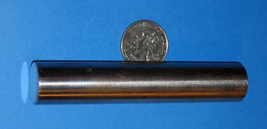
- The precision stainless-steel spheres are attached to the ends of the bar by gluing. A steel pin is inserted into a hole in the sphere and in the bar as the high strength glue is applied during assembly. The result is an exceptionally strong bond between the sphere and the bar.
To provide a stiff, lightweight assembly, the bar itself is made of 3/4 inch (19.05 mm) diameter heavy walled steel tubing.
This steel tubing is electroless nickel-plated to avoid corrosion.
Exploded View of the Ball Bar, the Pins Are Glued and Are Not Removable - Temperature
- Ball Bar (Dumbbell)s are much longer than most familiar gages and are therefore far more susceptible to temperature influence. Our Standard Ball Bar (Dumbbell)s have the same coefficient of thermal expansion as most steel and iron (6.3 microinches per inch per degree Fahrenheit, 11.4 micrometers per meter per degree Celsius).
The most frequent source of rapid thermal change is caused by the machine's operator handling the Ball Bar (Dumbbell). Even when wearing well insulated gloves, the Ball Bar (Dumbbell) should be handled as little as possible. The Ball Bar (Dumbbell) should be allowed to soak in the C.M.M. environment for 30 minutes for ordinary quality machines and two hours before taking any serious measurements.
Pricing, Standard Ball Bar, Steel
| Part # | Description | Price | Purchase |
|---|---|---|---|
| PBB-100 | BALL BAR, PRECISION, STEEL 0100 MM, 3.937 INCHES | $363.00 | |
| PBB-200 | BALL BAR, PRECISION, STEEL 0200 MM, 7.874 INCHES | $429.00 | |
| PBB-300 | BALL BAR, PRECISION, STEEL 0300 MM, 11.8 INCHES | $435.00 | |
| PBB-350 | BALL BAR, PRECISION, STEEL 0350 MM, 13.779 INCHES | $435.00 | |
| PBB-400 | BALL BAR, PRECISION, STEEL 0400 MM, 15.748 INCHES | $447.00 | |
| PBB-450 | BALL BAR, PRECISION, STEEL 0450 MM, 17.7 INCHES | $425.00 | |
| PBB-500 | BALL BAR, PRECISION, STEEL 0500 MM, 19.685 INCHES | $425.00 | |
| PBB-550 | BALL BAR, PRECISION, STEEL 0550 MM, 21.653 INCHES | $428.00 | |
| PBB-600 | BALL BAR, PRECISION, STEEL 0600 MM, 23.622 INCHES | $437.00 | |
| PBB-650 | BALL BAR, PRECISION, STEEL 0650 MM, 25.59 INCHES | $437.00 | |
| PBB-700 | BALL BAR, PRECISION, STEEL 0700 MM, 27.559 INCHES | $439.00 | |
| PBB-750 | BALL BAR, PRECISION, STEEL 0750 MM, 29.528 INCHES | $439.00 | |
| PBB-800 | BALL BAR, PRECISION, STEEL 0800 MM, 31.496 INCHES | $453.00 | |
| PBB-850 | BALL BAR, PRECISION, STEEL 0850 MM, 33.464 INCHES | $457.00 | |
| PBB-900 | BALL BAR, PRECISION, STEEL 0900 MM, 35.433 INCHES | $457.00 | |
| PBB-950 | BALL BAR, PRECISION, STEEL 0950 MM, 37.401 INCHES | $465.00 | |
| PBB-1000 | BALL BAR, PRECISION, STEEL 1000 MM, 39.37 INCHES | $465.00 | |
| PBB-1100 | BALL BAR, PRECISION, STEEL 1100 MM, 43.307 INCHES | $594.00 | |
| PBB-1600 | BALL BAR, PRECISION, STEEL 1600 MM, 62.992 INCHES | $636.00 | |
Pricing, Standard Ball Bar, Invar®
| Part # | Description | Price | Purchase |
|---|---|---|---|
| PBB-INV-100 | BALL BAR, PRECISION, INVAR® 0100 MM, 3.937 INCHES | $473.00 | |
| PBB-INV-200 | BALL BAR, PRECISION, INVAR® 0200 MM, 7.874 INCHES | $517.00 | |
| PBB-INV-300 | BALL BAR, PRECISION, INVAR® 0300 MM, 11.8 INCHES | $523.00 | |
| PBB-INV-350 | BALL BAR, PRECISION, INVAR® 0350 MM, 13.779 INCHES | $523.00 | |
| PBB-INV-400 | BALL BAR, PRECISION, INVAR® 0400 MM, 15.748 INCHES | $535.00 | |
| PBB-INV-450 | BALL BAR, PRECISION, INVAR® 0450 MM, 17.7 INCHES | $535.00 | |
| PBB-INV-500 | BALL BAR, PRECISION, INVAR® 0500 MM, 19.685 INCHES | $538.00 | |
| PBB-INV-550 | BALL BAR, PRECISION, INVAR® 0550 MM, 21.653 INCHES | $538.00 | |
| PBB-INV-600 | BALL BAR, PRECISION, INVAR® 0600 MM, 23.622 INCHES | $547.00 | |
| PBB-INV-650 | BALL BAR, PRECISION, INVAR® 0650 MM, 25.59 INCHES | $547.00 | |
| PBB-INV-700 | BALL BAR, PRECISION, INVAR® 0700 MM, 27.559 INCHES | $551.00 | |
| PBB-INV-750 | BALL BAR, PRECISION, INVAR® 0750 MM, 29.528 INCHES | $551.00 | |
| PBB-INV-800 | BALL BAR, PRECISION, INVAR® 0800 MM, 31.496 INCHES | $628.00 | |
| PBB-INV-850 | BALL BAR, PRECISION, INVAR® 0850 MM, 33.464 INCHES | $580.00 | |
| PBB-INV-900 | BALL BAR, PRECISION, INVAR® 0900 MM, 35.433 INCHES | $580.00 | |
| PBB-INV-950 | BALL BAR, PRECISION, INVAR® 0950 MM, 37.401 INCHES | $594.00 | |
| PBB-INV-1000 | BALL BAR, PRECISION, INVAR® 1000 MM, 39.37 INCHES | $594.00 | |
| PBB-INV-1100 | BALL BAR, PRECISION, INVAR® 1100 MM, 43.307 INCHES | $594.00 | |
| PBB-INV-1600 | BALL BAR, PRECISION, INVAR® 1600 MM, 62.992 INCHES | $636.00 | |
Adjustable Ball Bars for CMM Evaluation
The concept of the Ball Bar is almost too simple. Two very round, dimensionally matched spheres are securely attached to opposite ends of a rather long rigid bar. The center to center distance between these two spheres will remain constant regardless of what X-Y-Z position the bar may be held in. In practice, the center to center distance between the two spheres is measured many times while the Ball Bar is relocated in a variety of positions throughout the Coordinate Measuring Machines dimensional envelope. Any variation in these measurements indicates an error in the CMM System.
The Adjustable Ball Bar Kit is made as versatile as possible. A complete eight piece kit will allow for assembly of Ball Bars with sphere center to center dimensions from 100mm (3.937 inch) to 1650mm (64.96 inch), in 50mm (1.969 inch) increments. The precision spheres incorporated in the adjustable Ball Bar are made of ultra fine grain, high chrome, high carbon, stainless-steel. They are hardened to 58 HRC for wear-resistance and ultra cold-cycled for long term dimensional stability. The quality of the spheres meet all of the requirements for Performance Evaluation of Coordinate Measuring Machines ANSI/ACME B89.4.1-1997. They are five times as accurate as high quality bearing balls, They are precision lapped spherical within 5 millionths of an inch (127nm) with a maximum surface roughness of 0.5 micro inches (12.7nm) Ra.
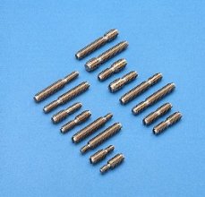
These precise spheres are not just glued on to the mounting posts. A steel pin is inserted into a deep, small diameter, hole in the sphere and in the post as the high strength glue is applied during assembly. The result is an exceptionally strong bond between the sphere and the post. The dimension from the flat end of the post to the sphere center is 50mm (1.969 inch).
There is a 3/16 inch (0.1875", 4.7525 mm) diameter clearance hole drilled through the post and through the cylinder of each extension bar. We supply high tensile stainless-steel pins that are used as wrenches to assemble and remove the various components. The posts and the extension ends are provided with an attractive black oxide finish which resists corrosion.
The 50mm (1.969 inch) extension is machined from a solid steel bar. The extensions from 100mm (3.937 inch) to 800mm (31.496 inch) are an assembly. Two rugged steel plugs that are tapped to accept a 5/16 inch (7.9mm) threaded stud are joined to a 3/4 inch (19.05mm) heavy walled steel tube. This provides a very stiff light weight assembly. This steel tubing is electroless nickel plated to resist corrosion.
From a broad perspective, there are two ways to support a Ball Bar for CMM evaluation. The first and by far the simplest is the free standing Ball Bar. The center of the Ball Bar is clamped to the vertical post of a gage stand and the position of the spheres are measured a large number of times as the gage stand is moved to various locations within the measuring envelope of the CMM. This method is simple and inexpensive, but its accuracy is somewhat limited.
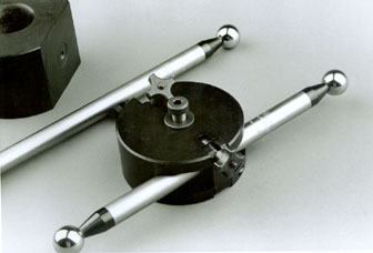
The force applied by the CMM measuring probe bends the shaft of the Ball Bar slightly; but the long unsupported lever formed by the Ball Bar twists and bends the vertical post of the support stand a considerable amount. Instead of causing a simple cosine error in the position of the spheres as might be expected, the Ball Bar is very unevenly deflected. The maximum deflection occurs perpendicular to the axis of the bar and is almost zero at the very ends. This condition is interpreted by the computer's spherical fit algorithm as a Ball Bar with smaller diameter spheres that are positioned further apart. This condition can be minimized by using a very robust vertical stand such as the "FS" series (see Technical Data Sheet CMM 2) or it can be all but eliminated by supporting the Ball Bar at its ends. The very rigid support is accomplished by using the truly cylindrical diameter of the optional accessory, ABB-C-PB-100. This cylinder is made of the same high quality, very fine grain, hardened stainless-steel as the spheres. The central area of this cylinder is precision lapped straight and round within 5 micro inches (127nm). This excellent cylinder makes intimate contact with the two balls of a Kinematic coupling (Part Number 2B-KM- Technical Data Sheet CMM3), so that not a single micro inch of backlash or hysteresis remains.
An extra feature of this coupling is a safety tether which consists of a loop of plastic covered steel cable that prevents a crash from sending the Ball Bar bouncing across the CMM table. The Ultra Precise Test Sphere at the opposite end of the Ball Bar is supported directly in the nest formed by the three .750" (19.05mm) hardened stainless-steel balls of the Kinematic Platform (Part Number 3B-KM, see Technical Data Sheet CMM-4). This platform can be solidly clamped to the CMM table through either a 3/8 inch or 10mm diameter socket head screw.
We strongly recommend that three of the post mounted precision spheres (Part Number ABB-PB100) be purchased at the time the set is acquired. The adjustable Ball bar requires assembly in the field where there is a high risk of damaging one of the spheres. Although we carry a good inventory of replacement spheres in stock, several days could elapse in their transportation to your site.
Each component in the Adjustable Ball Bar line is priced separately so that special combinations may be purchased to satisfy specific needs. When the main need is for evaluating very large gantry machines, several of the 800mm (31.496 inch) sections may be desirable. If the set is transported frequently, consider having the set broken down into several shorter bars.
Available Components for Adjustable Ball Bar Kit
| Part # | Bar Length | Metric | Description | Price | Purchase |
|---|---|---|---|---|---|
| ABB-25 | 0.984" | 25 mm | ADJUSTABLE BALL BAR LENGTH, 025 MM, 0.984 INCHES | $66.00 | |
| ABB-50 | 1.969" | 50 mm | ADJUSTABLE BALL BAR LENGTH, 050 MM, 1.968 INCHES | $66.00 | |
| ABB-100 | 3.937" | 100 mm | ADJUSTABLE BALL BAR LENGTH, 100 MM, 3.937 INCHES | $109.00 | |
| ABB-200 | 7.874" | 200 mm | ADJUSTABLE BALL BAR LENGTH, 200 MM, 7.874 INCHES | $115.00 | |
| ABB-400 | 15.748" | 400 mm | ADJUSTABLE BALL BAR LENGTH, 400 MM, 15.748 INCHES | $120.00 | |
| ABB-600 | 23.622" | 600 mm | ADJUSTABLE BALL BAR LENGTH, 600 MM, 23.62 INCHES | $121.00 | |
| ABB-800 | 31.496" | 800 mm | ADJUSTABLE BALL BAR LENGTH, 800 MM, 31.496 INCHES | $123.00 | |
| ABB-INV-50 | 1.969" | 50 mm | ADJUSTABLE BALL BAR LENGTH, INVAR®, 050 MM, 1.968 INCHES | $176.00 | |
| ABB-INV-100 | 3.937" | 100 mm | ADJUSTABLE BALL BAR LENGTH, INVAR®, 100 MM, 3.937 INCHES | $219.00 | |
| ABB-INV-200 | 7.874" | 200 mm | ADJUSTABLE BALL BAR LENGTH, INVAR®, 200 MM, 7.874 INCHES | $225.00 | |
| ABB-INV-400 | 15.748" | 400 mm | ADJUSTABLE BALL BAR LENGTH, INVAR®, 400 MM, 15.748 INCHES | $230.00 | |
| ABB-INV-600 | 23.622" | 600 mm | ADJUSTABLE BALL BAR LENGTH, INVAR®, 600 MM, 23.62 INCHES | $231.00 | |
| ABB-INV-800 | 31.496" | 800 mm | ADJUSTABLE BALL BAR LENGTH, INVAR®, 800 MM, 31.496 INCHES | $233.00 | |
| ABB-INV-K | ADJUSTABLE BALL BAR KIT, INVAR® | $1617.00 | |
||
| ABB-PIN | ADJUSTABLE BALL BAR PIN | $19.25 | |
||
| ABB-PB-100 | 1" (Sphere Diameter) |
25.4 mm | POST MOUNTED SPHERE FOR ADJUSTABLE BALL BAR | $219.00 | |
| ABB-UP-100 | SPHERE AND CYLINDER | $301.00 | |
||
| ABB-K | ADJUSTABLE BALL BAR KIT, EIGHT PIECES | $1133.00 | |
||
| ABB-K-CASE | ADJUSTABLE BALL BAR KIT, STEEL WITH CASE | $1463.00 | |
||
| ABB-CASE | ADJUSTABLE BALL BAR CASE, RIGID PLASTIC | $330.00 | |
||
| ABB-INV-K-CASE | ADJUSTABLE BALL BAR KIT, INVAR®, WITH CASE | $1947.00 | |
In addition to the standard components listed, a wide variety of custom made items can be economically produced. Some of the more common of these include extra long extensions made of larger diameter tubing for greater rigidity, spheres of different diameters or materials, kits made of special materials to meet specific thermal expansion characteristics, and magnetic sockets.
Dual Threaded Adaptor Screw
We carry a full line of Dual Threaded Adaptor Screws which have a different thread on each end. These threaded adaptors will match all of our Coordinate Measuring Machine evaluation and fixture building devices to the threads in the table of any C.M.M. or competitor's pallet system. The short version of these threaded adaptors (Table #1) have an overall length of 1.5 inches (38.1 mm) and each of the threads is 3/4 inch (19 mm) long, except the 1/4 inch-20 to M10 x 1.5, where the 1/4 inch diameter is only 1/2 inch (13 mm) long.
| Part # | Table Thread Size | Component Thread Size | Price | Purchase |
|---|---|---|---|---|
| S-8M-10M | M 8 x 1.25 x 3/4" ( 19 mm ) | M 10 x 1.5 x 3/4" ( 19 mm ) | $18.43 | |
| S-10M-10M | M 10 x 1.5 x 3/4" ( 19 mm ) | M 10 x 1.5 x 3/4" ( 19 mm ) | $18.43 | |
| S-12M-10M | M 12 x 1.75 x 3/4" ( 19 mm ) | M 10 x 1.5 x 3/4" ( 19 mm ) | $18.43 | |
| S-250-10M | 1/4" - 20 x 1/2" ( 13 mm ) | M 10 x 1.5 x 3/4" ( 19 mm ) | $18.43 | |
| S-312-10M | 5/16" - 18 x 3/4" ( 19 mm ) | M 10 x 1.5 x 3/4" ( 19 mm ) | $18.43 | |
| S-375-10M | 3/8" - 16 x 3/4 ( 19 mm ) | M 10 x 1.5 x 3/4" ( 19 mm ) | $18.43 | |
| S-500-10M | 1/2" - 13 x 3/4" ( 19 mm ) | M 10 x 1.5 x 3/4" ( 19 mm ) | $18.43 | |
Because these Dual Threaded Adaptor Screws get such heavy use, we machine a reduced-diameter on the very ends to avoid damaging the thread. The two threads have an undercut in the center to allow either of the threads to be tightened fully without any chance of binding. The Dual Threaded Adaptor Screws will not rust because they are manufactured from a very corrosive resistant type 18-8 stainless-steel. The highest quality threads with increased tensile strength are produced by cold rolling the thread forms. There is a screwdriver slot provided at the end of each thread of the short version and in the long threaded end of the long version. With the aid of a coin or screwdriver, the Dual Threaded Adaptor Screw can be securely tightened into its mating part.
The long version of these Dual Threaded Adaptor Screws (Table #2) have an overall length of 2.5 inches (76.2mm). The table, or short end thread, is 3/4 inch (1.9 cm) long; and the M10 x 1.5 thread is 1.75 inches (44.5 mm) long, except the 1/4 inch-20 to M10 x 1.5, where the 1/4 inch diameter thread is only 1/2 inch (13 mm) long. If one of these fourteen combinations does not meet your requirements, we will be pleased to supply any other combination on special order.
| Part # | Table Thread Size | Component Thread Size | Price | Purchase |
|---|---|---|---|---|
| L-8M-10M | M 8 x 1.25 x 3/4" ( 19 mm ) | M 10 X 1.5 X 1 3/4" ( 44.5 mm ) | $18.43 | |
| L-10M-10M | M 10 x 1.5 x 3/4" ( 19 mm ) | M 10 x 1.5 x 1 3/4" ( 44.5 mm ) | $18.43 | |
| L-12M-10M | M 12 x 1.75 x 3/4" ( 19 mm ) | M 10 x 1.5 x 1 3/4" ( 44.5 mm ) | $18.43 | |
| L-250-10M | 1/4" - 20 x 1/2" ( 13 mm ) | M 10 x 1.5" x 1 3/4" ( 44.5 mm ) | $18.43 | |
| L-312-10M | 5/16" - 18 x 3/4" ( 19 mm ) | M 10 x 1.5 x 1 3/4" ( 44.5 mm ) | $18.43 | |
| L-375-10M | 3/8" - 16 x 3/4" ( 13 mm ) | M 10 x 1.5 x 1 3/4" ( 44.5 mm ) | $18.43 | |
| L-500-10M | 1/2" - 13 x 3/4" ( 19 mm ) | M 10 x 1.5 x 1 3/4" ( 44.5 mm ) | $18.43 | |
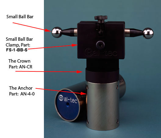
The Ball Bar (Dumbbell) Anchor
The Ball Bar (Dumbbell) Anchor™ is a good alternative to a Heavy Duty Stand for rigidly supporting Ball Bar (Dumbbell)s during Coordinate Measuring Machine Evaluation. The key feature of the Anchor is its very light weight. It comes in five standard lengths. The shortest is the four inch ( 10.0 cm) (Part #AN-4-0) version which is only used as an extension to lengthen the other longer Anchors. The 8 inch version (20.3 cm) (Part #AN-8-0) weighs only three pounds (1.36 kilograms), the 12 inch (30.5 cm) version (Part #AN-12-0) weighs four and one half pounds (2.04 kilograms), and the 24 inch (61 cm) version (Part #AN-24-0) weighs seven and three quarters pounds (3.5 kilograms). The collar (Part #AN-1) and Ball Bar (Dumbbell) holding clamp (Part #FS-1) together weigh 8.2 pounds (3.7 kg).
For a number of Ball Bar (Dumbbell) applications, the standard Heavy Duty Stand is not suitable. The shortest Heavy Duty Stand is 14 inches high. This is simply too tall for very small machines. The average 30 pound (13.6 kg) weight of the Heavy Duty Stand is too heavy for some machines. Its lack of symmetry makes the Heavy Duty Stand awkward to position in very close quarters. The 30 pound (13.6 kg) weight of the Heavy Duty Stand with its low center of gravity is very mechanically stable, but it is also a very heavy burden when it has to be carried all over the country on an airplane.
The Anchor is a simple, well engineered alternative method of Ball Bar support. Versions of this device have been well tested in the field over many years. The Anchor is constructed from three inch (7.6 cm) diameter steel tubing that is precision ground and hard coated. It is pulled securely down to the C.M.M. table by a threaded stud. This stud is screwed into the threaded center hole in one of the thick aluminum bulkheads, located in each end of the Anchor.
The Anchor is a very versatile tool. It can use the simple single clamping block for holding one Ball Bar (Dumbbell) (Part #FS-1BB), or the Over and Under clamp which holds two parallel Ball Bar (Dumbbell)s (Part #FS-2BB). It will hold any of the Way Out Ball Bar (Dumbbell) supports (see Technical Data Sheet C.M.M.-16, Page 2.). The Anchor has an M10x1.5 threaded hole through the center of the top and bottom bulkheads so two or more of the Anchors can be threaded together, one on top of the other to multiply their height.
A full array of Dual Threaded Adaptor Screws are offered that will match the Anchor to the threads in the table of any C.M.M. (see Technical Data Sheet C.M.M.-14 Table #1.). The adaptor screws are not included. A disk mounted, two ball, Kinematic coupling (Part #2B-KM-A) (see this Technical Data Sheet #) is offered to rigidly hold the Ultra Precise Ball Bar (Dumbbell)s (see Technical Data Sheet C.M.M.-5.). It can be attached to the top of any height Anchor through the upper threaded bulkhead. A powerful rare earth magnet holds the Ball Bar in position. The magnet is embedded in the rigid aluminum disk between the two balls that form this kinematic coupling.
The Abalone (Part #10140) is a vacuum hold down foot that is one and a quarter inch (31.75mm) thick and five inches (127mm) in diameter. It is simple to install on the bottom of the Anchor through the M10x1.5 thread. With a good vacuum pump, the Abalone can provide 290 pounds (131 kg) of holding force (see Technical Data Sheet C.M.M.-13, Page 1.).
The four inch (10.2 cm) diameter Magnetic Base (Part #M-PLT4) (see Technical Data Sheet C.N.C.-2) gives added versatility to the Anchor by allowing it to be rigidly mounted on steel and Cast Iron Surfaces.
| Part # | Description | Price | Purchase |
|---|---|---|---|
| AN-1 | COLLAR, 3 INCH, FOR ANCHOR OR MAMMOTH | $136.00 | |
| AN-12 | ANCHOR WITH COLLAR AND FS-1BB 304.8 MM, 12 INCHES | $617.00 | |
| AN-12-0 | ANCHOR ONLY 304.8 MM, 12 INCHES | $343.00 | |
| AN-24 | ANCHOR WITH COLLAR AND FS-1BB 609.6 MM, 24 INCHES | $656.00 | |
| AN-24-0 | ANCHOR ONLY 609.6 MM, 24 INCHES | $382.00 | |
| AN-3 | COLLAR, TRI-MOUNT FOR ANCHOR | $274.00 | |
| AN-36 | ANCHOR WITH COLLAR AND FS-1BB 914.4 MM, 36 INCHES | $695.00 | |
| AN-36-0 | ANCHOR ONLY 914.4 MM, 36 INCHES | $421.00 | |
| AN-4 | ANCHOR WITH COLLAR AND FS-1BB 101.6 MM, 4 INCHES | $585.00 | |
| AN-4-0 | ANCHOR ONLY 101.6 MM, 4 INCHES | $311.00 | |
| AN-8 | ANCHOR WITH COLLAR AND FS-1BB 203.2 MM, 8 INCHES | $585.00 | |
| AN-8-0 | ANCHOR ONLY 203.2 MM, 8 INCHES | $278.00 | |
| AN-CR | CROWN FOR ANCHOR | $181.00 | |
The Archival Ball Bar (Dumbbell) is a Three Dimensional Gage Block
This device adds a new level of accuracy and flexibility to the evaluation of Coordinate Measuring Machines. The Archival Ball Bar Dumbbell) substantially exceeds the accuracy requirements of the ANSI B89.4.1-1997 for the "Performance Evaluation of Coordinate Measuring Machines”.
This device consists of two ultra precise spheres that are securely mounted in spherical seats at the end of a rather long rigid bar. The contact end of the ultra precise spheres mate with very precisely machined female spherical cups in each end of the bar. This design makes the Archival Ball Bar (Dumbbell) a true three dimensional gage block. The sphere center to center dimension is always very accurately calibrated. This calibration is made traceable to The National Institute for Standards and Technology, and through them to the International Standard of Length.
The material for the bar of this device is a special alloy metal that is heat treated for very long term dimensional stability. All of the metal used for construction of the Archival Ball Bar (Dumbbell) has a normal thermal coefficient of expansion of 6.2 microinches per inch per degree Fahrenheit or 11.4 micrometers per meter per degree Celsius. This makes them compatible with all steel and iron products.
The bars for the Archival Ball Bar (Dumbbell)s can also be produced from Invar®, a nickel iron alloy that has almost zero thermal coefficient of expansion. This material is expensive, and its long term dimensional stability is uncertain. The spheres for the Archival Ball Bar (Dumbbell) are manufactured from high chrome, high carbon stainless-steel. This material is through hardened to 58 Rockwell C and thermal cycled for long term dimensional stability. The roundness of the spheres is held within 2.5 micro inches (63.5 nm) and the two spheres are matched for size within 2.5 microinches (63.5 nm). The absolute size of any of the spheres sold for use on Archival Ball Bar (Dumbbell)s are precision lapped to an absolute size tolerance of 10 microinches (25.4 nm). The standard diameter for the Spheres of the Archival Ball Bar (Dumbbell)s is 1.00 inch (25.4 mm) but other diameters will be supplied for special applications.
The Archival Ball Bar (Dumbbell) is usually supplied in the Cantilevered Ball Bar (Dumbbell) design (see Technical Data Sheet .). The Cantilevered design has two additional spheres mounted just behind the master spheres so the Ball Bar (Dumbbell) can be Kinematically supported for greater rigidity and to provide better exposure of the master spheres for measurement. The ideal support for this Archival standard is the Way Out Ball Bar (Dumbbell) Support (see Technical Data Sheet C.M.M.-16, Page 2.).
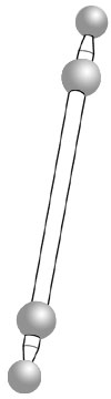
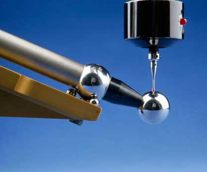
The Cantilever Ball Bar
A basic Ball Bar (Dumbbell) consists of two very precise spheres of exactly the same diameter securely attached to the opposite ends of a rather long rigid bar. The Cantilever design Ball Bar (Dumbbell) provides a method of rigid support for the Ball Bar that virtually eliminates any bending due to the contact force of the measuring probe. The Cantilever Ball Bar (Dumbbell) has two additional spheres placed just behind the master spheres. This second set of spheres are used as a means for rigidly supporting the Ball Bar (Dumbbell).
The two, one inch (2.54cm) diameter master spheres are lapped spherical within 2.5 microinches (63nm) and have a surface finish of less then .5 micro inches (13nm) Ra or Arithmetic Average.
Cantilever Ball Bar Pricing, Steel
The master spheres are manufactured from high chrome, high carbon stainless-steel that has ultra fine grain structure. The master spheres are hardened to 58 HRC and thermo cycled for long term dimensional stability. The 3/4 inch (1.9cm) diameter tubular steel construction provides a very rigid light weight structure. The Ultra Precise stainless-steel spheres are attached to the ends of the Ball Bar (Dumbbell) by gluing. A steel pin is inserted into a drilled hole in the master sphere and in the bar as the high strength glue is applied during assembly. The result is an exceptionally strong, shock resistant, bond between the master sphere and the bar.
The two support spheres are held in two magnetically pre-loaded kinematic couplings attached to a very rigid tee shaped aluminum rail of the Way Out Ball Bar (Dumbbell) Support (see Technical Data Sheet C.M.M.-16, Page 2.). The first kinematic coupling consists of three precision spheres arranged in a circle to form a three contact cup. The second kinematic coupling consists of two precision cylinders that form a dual contact cradle. Each of these kinematic couplings has a powerful rare earth magnet implanted just below the surface in the center of the coupling.
This design constrains five of the six degrees of Ball Bar freedom without introducing any over constraint. The Cantilever design provides three outstanding advantages over the conventional free standing Ball Bar. The most important advantage is the very rigid support it provides. This design virtually eliminates any of the deflections caused by the contact force of the measuring probe. The second advantage is that the master spheres are never contacted by the kinematic couplings which might cause scratching, wear or brinelling. The third advantage is that the entire surfaces of the master spheres are exposed for evaluation by the C.M.M. measuring probe. The Cantilever Ball Bar is usually used with The Way Out Rail, see page: CMM-16, Page 2.
| Part # | Description | Price | Purchase |
|---|---|---|---|
| CUP-BB-200 | BALL BAR, CANTILEVER, STEEL, 0200 MM, 7.874 INCHES | $652.00 | |
| CUP-BB-300 | BALL BAR, CANTILEVER, STEEL, 0300 MM, 11.8 INCHES | $652.00 | |
| CUP-BB-350 | BALL BAR, CANTILEVER, STEEL, 0350 MM, 13.779 INCHES | $664.00 | |
| CUP-BB-400 | BALL BAR, CANTILEVER, STEEL, 0400 MM, 15.748 INCHES | $675.00 | |
| CUP-BB-450 | BALL BAR, CANTILEVER, STEEL, 0450 MM, 17.7 INCHES | $688.00 | |
| CUP-BB-500 | BALL BAR, CANTILEVER, STEEL, 0500 MM, 19.685 INCHES | $688.00 | |
| CUP-BB-550 | BALL BAR, CANTILEVER, STEEL, 0550 MM, 21.653 INCHES | $699.00 | |
| CUP-BB-600 | BALL BAR, CANTILEVER, STEEL, 0600 MM, 23.622 INCHES | $699.00 | |
| CUP-BB-650 | BALL BAR, CANTILEVER, STEEL, 0650 MM, 25.59 INCHES | $722.00 | |
| CUP-BB-700 | BALL BAR, CANTILEVER, STEEL, 0700 MM, 27.559 INCHES | $722.00 | |
| CUP-BB-750 | BALL BAR, CANTILEVER, STEEL, 0750 MM, 29.528 INCHES | $734.00 | |
| CUP-BB-800 | BALL BAR, CANTILEVER, STEEL, 0800 MM, 31.496 INCHES | $734.00 | |
| CUP-BB-850 | BALL BAR, CANTILEVER, STEEL, 0850 MM, 33.464 INCHES | $746.00 | |
| CUP-BB-900 | BALL BAR, CANTILEVER, STEEL, 0900 MM, 35.433 INCHES | $746.00 | |
| CUP-BB-950 | BALL BAR, CANTILEVER, STEEL, 0950 MM, 37.401 INCHES | $769.00 | |
| CUP-BB-1000 | BALL BAR, CANTILEVER, STEEL, 1000 MM, 39.37 INCHES | $769.00 | |
Cantilever Ball Bar Pricing, Invar®
| Part # | Description | Price | Purchase |
|---|---|---|---|
| CUP-BB-INV-200 | BALL BAR, CANTILEVER, INVAR®, 0200 MM, 7.874 INCHES | $782.00 | |
| CUP-BB-INV-300 | BALL BAR, CANTILEVER, INVAR®, 0300 MM, 11.8 INCHES | $782.00 | |
| CUP-BB-INV-350 | BALL BAR, CANTILEVER, INVAR®, 0350 MM, 13.779 INCHES | $794.00 | |
| CUP-BB-INV-400 | BALL BAR, CANTILEVER, INVAR®, 0400 MM, 15.748 INCHES | $805.00 | |
| CUP-BB-INV-450 | BALL BAR, CANTILEVER, INVAR®, 0450 MM, 17.7 INCHES | $816.00 | |
| CUP-BB-INV-500 | BALL BAR, CANTILEVER, INVAR®, 0500 MM, 19.685 INCHES | $816.00 | |
| CUP-BB-INV-550 | BALL BAR, CANTILEVER, INVAR®, 0550 MM, 21.653 INCHES | $828.00 | |
| CUP-BB-INV-600 | BALL BAR, CANTILEVER, INVAR®, 0600 MM, 23.622 INCHES | $828.00 | |
| CUP-BB-INV-650 | BALL BAR, CANTILEVER, INVAR®, 0650 MM, 25.59 INCHES | $828.00 | |
| CUP-BB-INV-700 | BALL BAR, CANTILEVER, INVAR®, 0700 MM, 27.559 INCHES | $851.00 | |
| CUP-BB-INV-750 | BALL BAR, CANTILEVER, INVAR®, 0750 MM, 29.528 INCHES | $864.00 | |
| CUP-BB-INV-800 | BALL BAR, CANTILEVER, INVAR®, 0800 MM, 31.496 INCHES | $864.00 | |
| CUP-BB-INV-850 | BALL BAR, CANTILEVER, INVAR®, 0850 MM, 33.464 INCHES | $864.00 | |
| CUP-BB-INV-900 | BALL BAR, CANTILEVER, INVAR®, 0900 MM, 35.433 INCHES | $898.00 | |
| CUP-BB-INV-950 | BALL BAR, CANTILEVER, INVAR®, 0950 MM, 37.401 INCHES | $898.00 | |
| CUP-BB-INV-1000 | BALL BAR, CANTILEVER, INVAR®, 1000 MM, 39.37 INCHES | $898.00 | |
The Way Out Ball Bar (Dumbbell) Support
A Ball Bar (Dumbbell) is the major tool for functional "Performance Evaluation of Coordinate Measuring Machines" According to ANSI B89.4.1-1997. A Ball Bar (Dumbbell) consists of two very round spheres of exactly the same size firmly attached to opposite ends of a rather long rigid bar. The accuracy of a Ball Bar (Dumbbell) has a single major limitation.
A conventional free standing Ball Bar (Dumbbell) will bend when the contact force of the measuring probe is applied to it. The longer the Ball Bar (Dumbbell), the greater the bending. With all of the automatic error correcting computer power, it should be easy enough to compensate for these Ball Bar (Dumbbell) deflections. However, these corrections turn out to be a good deal more complex than they first appear. The resulting deflection of the Ball is a rather complex vector function of gravitational sag, some simple bending and a large twisting moment. This is all complicated by the fact that there is no deflection at all on the very ends of the Ball Bar (Dumbbell). The end result of this complexity is that the C.M.M. and its software see two much smaller diameter spheres with the distance between their centers much further apart then the true dimension.
For C.M.M.s of ordinary quality, these shortcomings are of little or no consequence. The bending is fairly repeatable and the limited resolution and accuracy of ordinary machines presented little challenge for the free standing Ball Bar (Dumbbell). With the advent of the new generation of high end C.M.M.s, a new higher accuracy Ball Bar (Dumbbell) is required. An advance in Ball Bar (Dumbbell) technology now corrects these errors by providing two additional spheres just behind the master spheres. These two hardened steel spheres are rigidly attached to the Ball Bar (Dumbbell) shaft. The additional spheres are used to Kinematically support the Ball Bar (Dumbbell) in a very rigid manner, while leaving the full surfaces of the master spheres exposed for measurement.
These two kinematic couplings that support the Ball Bar (Dumbbell) are mounted near the very ends of a robust aluminum supporting structure that resists all bending. The very rigid aluminum structure is only used as a support mechanism for the Ball Bar (Dumbbell). Its high rate of thermal expansion does not in any way influence the inter ball dimension of the steel Ball Bar (Dumbbell) itself.
The kinematic coupling that holds the first support sphere consists of three precision spheres located in a circle and rigidly mounted to the aluminum structure. The other coupling consists of two precision lapped cylinders rigidly mounted to the aluminum structure, to form a Vee-Block, that locates the second support sphere. There is a powerful rare earth magnet just below each of the couplings that pulls the support spheres solidly down against the kinematic couplings.
Way Out Ball Bar Support Pricing
| Part # | Description | Price | Purchase |
|---|---|---|---|
| WO-300 | WAY OUT RAIL, FOR 0300 MM CANTILEVER BALL BAR, SOLD SEPARATELY | $657.00 | |
| WO-400 | WAY OUT RAIL, FOR 0400 MM CANTILEVER BALL BAR, SOLD SEPARATELY | $657.00 | |
| WO-450 | WAY OUT RAIL, FOR 0450 MM CANTILEVER BALL BAR, SOLD SEPARATELY | $657.00 | |
| WO-500 | WAY OUT RAIL, FOR 0500 MM CANTILEVER BALL BAR, SOLD SEPARATELY | $540.00 | |
| WO-550 | WAY OUT RAIL, FOR 0550 MM CANTILEVER BALL BAR, SOLD SEPARATELY | $540.00 | |
| WO-600 | WAY OUT RAIL, FOR 0600 MM CANTILEVER BALL BAR, SOLD SEPARATELY | $686.00 | |
| WO-650 | WAY OUT RAIL, FOR 0650 MM CANTILEVER BALL BAR, SOLD SEPARATELY | $656.00 | |
| WO-700 | WAY OUT RAIL, FOR 0700 MM CANTILEVER BALL BAR, SOLD SEPARATELY | $676.00 | |
| WO-750 | WAY OUT RAIL, FOR 0750 MM CANTILEVER BALL BAR, SOLD SEPARATELY | $693.00 | |
| WO-800 | WAY OUT RAIL, FOR 0800 MM CANTILEVER BALL BAR, SOLD SEPARATELY | $769.00 | |
| WO-850 | WAY OUT RAIL, FOR 0850 MM CANTILEVER BALL BAR, SOLD SEPARATELY | $781.00 | |
| WO-900 | WAY OUT RAIL, FOR 0900 MM CANTILEVER BALL BAR, SOLD SEPARATELY | $812.00 | |
| WO-200 | WAY OUT RAIL, FOR 0200 MM CANTILEVER BALL BAR, SOLD SEPARATELY | $721.00 | |
| WO-1000 | WAY OUT RAIL, FOR 1000 MM CANTILEVER BALL BAR, SOLD SEPARATELY | $822.00 | |
| WO-1600 | WAY OUT RAIL, FOR 1600 MM CANTILEVER BALL BAR, SOLD SEPARATELY | $834.00 | |
Ball Bar - Dumbbell Case Studies
A very large machine tool manufacturer had just installed a giant C.M.M. in a newly constructed temperature controlled lab. The brand new machine was certified in place by the C.M.M. Manufacturer. This machine tool manufacturer was getting some measurements that disturbed them. They purchased our 900mm cantilevered Ball Bar on a way out Ball Bar support. This 900mm Ball Bar was held on the machine by our 36 inch tall Heavy Duty Stand.
They called a week later to complain that there was something very wrong with their Ball Bar. They knew that the error was in the Ball Bar, because when they measured it in line with any axis, in any position and at any elevation it measured exactly the same length, but as soon as they inclined the Ball Bar at an angle, the readings were all over the place. We politely informed this customer that what they were measuring were the errors in the C.M.M.
We sold one of our Ball Bar Kits to a young man who was having problems with his C.M.M. One week later, he call to discuss the results. His C.M.M. had just been serviced and certified by the machine's manufacturer at a cost of $700.00. The Ball Bar found that the “Z” axis was out of square with the “X” axis 0.009” (0.23 mm). The “Z” to “Y” Axii were perfectly square. After adjusting “Z”-“X” the entire machine was measuring within 0.0003” (0.076mm). He wondered if we had any suggestions on how he might improve this. As this was an older manual machine, we told him that we thought this was an acceptable accuracy.
A simple, inexpensive Ball Bar-Dumbbell system provides legal certification according to ANSI B 89.4.1 or VIM-VAR.
CMM Clamping Devices
All of our Ball Bar clamping devices are designed to be very quick acting, so that only brief hand contact is required when loading them; and no contact is required when changing the angle, the position, or the elevation of the Ball Bar.
The Tri-mount Collar for Ball Bar Stands
The Tri-Mount Ball Bar Collar™ is an improvement in the tools for Coordinate Measuring Machine evaluation. The fundamental design of the Tri-Mount allows it to hold three or more separate Ball Bars all at the same time. It is machined to form a collar that wraps around the vertical post of the stand. A slot is used to lock this rear block in place.
It is capable of holding as many as three Ball Bar Clamps at the same time, also referred to as the front blocks. Using three dual Ball Bar clamps, the Tri-Mount could potentially hold as many as six Ball Bars. With one Ball Bar held vertical, one held horizontal and one held at an angle, all of the twenty positions specified in the ANSI B89.4.1-1997 standard can be achieved. A unique feature of this new device is that it totally eliminates any hand contact with the Ball Bar (Dumbbell) by the calibration technician. This is especially important because all Ball Bars are rather long devices which make them very sensitive to temperature change.
The location ports on the Tri-Mount will accept the Single Ball Bar clamp (Part #FS-1BB), the Dual Ball Bar Clamp (Part # FS-2BB), the Small Ball Bar Clamp, (Part #FS-1BB-S) or any length of the Way Out Ball Bar Supports.
Important Note:
If the Ball Bar you need is 100 or 200 millimeters in length, you will need a small Ball Bar clamp to hold it. The distance between the balls on these Ball Bars will not clear the clamping fixture itself.
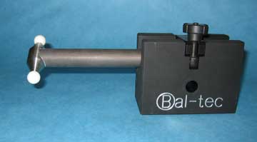
The front block is fitted with a long Vee Block which is used to securely hold the Ball Bar (Dumbbell). The front block will allow the Ball Bar (Dumbbell) to rotate a full 360° parallel to the vertical post, allowing a full range of positioning. Both of the blocks are hard anodized for wear resistance. The Single Ball Bar Clamp is four inches wide (4.0”, 101.6 mm).
To install a Ball Bar in the free standing Ball Bar clamping device, first loosen the cap screw and set the clamp horizontal, with the Vee-Block up. Next tighten the cap screw to secure the clamping device. Now loosen the four spoke locking knob and flip the clamping barback. Quickly place the Ball Bar in the Vee-Block and flip the clamping bar forward, then tighten the four spoke locking knob.
This new approach provides an economical artifact that is 100% compatible with all of our Ball Bar clamping devices. This simple approach allows even the shortest Ball Bar (Dumbbell) to be held on any of our standard Heavy Duty stands or any of the Anchor systems.
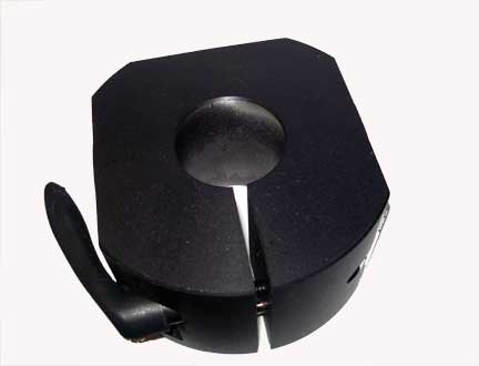
The Low Down Bar Clamp
There are 21 positions of the Ball Bar, required to do a full ANSI B89.4.1-1997 calibration of a Coordinate Measuring Machine. Some of those positions are the low horizontals.
For typical C.M.M.'s, the top of the heavy duty stand, where our standard Ball Bar Clamp) part FS-1BB will hold the Ball Bar, is low enough, but to hold to, the letter of the standard and for smaller coordinate measuring machines, where there isn’t that much, up and down, or “Z” axis height, you must use a special “Low Down” Ball Bar clamp, (part# FS-1BB-LOW).
When the collar on our standard heavy duty stand is lowered all the way down, while using the Low Down Ball Bar clamp, a standard Ball Bar will just touch the table of the C.M.M. This device is 2” thick, 4” wide, and 7 3/4" long, see the picture and the drawing. Low Down Ball Bar Clamp FS-1BB-LOW costs $178.00
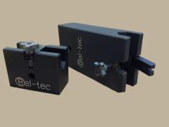
The Dual Ball Bar Clamp
A take off on the single Ball Bar for interim evaluation is The Ball Bar Kit where a special dual Ball Bar clamping device (Part # FS-2BB) is substituted for the standard single bar clamp. The two Ball Bars are usually one short 300 mm (11.8 inches) and one long 600 mm (23.6 inches) or 600 mm and 900 mm (35.4 inches), sphere center to center length.
The extra data points collected from the double Ball Bar device tend to show up short, wavy errors. The length of the Ball Bar or Ball Bars chosen for the interim check should be as long as possible but short enough to allow the holding device to be rotated on the C.M.M. table to form the four sides of a cube.
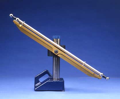
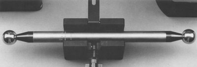
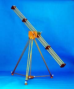
The Way Out Ball Bar Support Rail
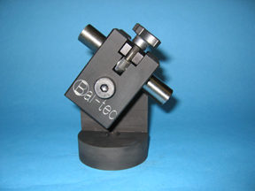
This device is a very rigid Tee shaped aluminum rail. It Kinematically supports the Ball Bar balls or as pictured here with the Cantilevered Ball Bar. This added support virtually eliminates any bending of the Ball Bar. In use, The Way Out Ball Bar Support is attached to the Tri-Mount collar on the Heavy Duty Stand or the Anchor. A socket head shoulder bolt passes through the center of the aluminum rail. The desired angle is set and the Way Out Support is clamped down.
Pricing
| Part # | Description | Price | Purchase |
|---|---|---|---|
| AN-1 | COLLAR, 3 INCH, FOR ANCHOR OR MAMMOTH | $136.00 | |
| AN-3 | COLLAR, TRI-MOUNT FOR ANCHOR | $274.00 | |
| FS-10M | STAND TIE DOWN | $62.57 | |
| FS-14 | BALL BAR STAND 355.6 MM, 14 INCHES, INCLUDES A SINGLE CLAMP, COLLAR | $628.00 | |
| FS-14-0 | BALL BAR STAND ONLY, 355.6 MM, 14 INCHES | $381.00 | |
| FS-14-3-6 | BALL BAR KIT, INCLUDES 300 MM AND 600 MM BALL BARS, STAND, A COLLAR AND DUAL CLAMP | $1367.00 | |
| FS-1BB | SINGLE BALL BAR CLAMP | $151.00 | |
| FS-1BB-S | SMALL BALL BAR CLAMP | $151.00 | |
| FS-24 | BALL BAR STAND 609.6 MM, 24 INCHES, INCLUDES A SINGLE CLAMP, A COLLAR AND A TIE DOWN | $650.00 | |
| FS-24-0 | BALL BAR STAND ONLY, 609.6 MM, 24 INCHES | $401.00 | |
| FS-2BB | DUAL BALL BAR CLAMP | $180.00 | |
| FS-3 | TRI-MOUNT COLLAR, 2 INCH DIAMETER THROUGH HOLE, FOR HEAVY DUTY STAND | $273.00 | |
| FS-36 | BALL BAR STAND 914.4 MM, 36 INCHES, INCLUDES A SINGLE CLAMP, A COLLAR AND A TIE DOWN | $683.00 | |
| FS-36-0 | BALL BAR STAND ONLY, 914.4 MM, 36 INCHES | $488.00 | |
| FS-3BB | TRI-MOUNT COLLAR AND THREE SINGLE BALL BAR CLAMPS | $604.00 | |
| FS-KIT-750 | PRE LOAD KIT FOR MECHANICAL CLAMPING | $377.00 | |
| FS-WB | WASHER AND SHOULDER BOLT | $10.80 | |
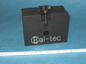
Small Ball Bar Clamp
This small Ball Bar Clamp, Part Number FS-1BB-S is intended to hold inspection devices on very small Coordinate Measuring Machines. The three-quarter inch (3/4", 19mm) diameter tube of the Ball Bar or cylindrical diameter of the gage block is held in the vee block of the clamp. Part Number GB-4 will meet the requirement of measuring a gage block which is now required by the revised ANSI B89.4.1-1997 specification for "Performance Evaluation of Coordinate Measuring Machines". This very small Ball Bar Clamp is only two inches (2.0", 50.8mm) wide, two inches (2.0", 50.8mm) thick and three inches (3.0", 76.2mm) high.
Important Note:
If the Ball Bar you need is 100 or 200 millimeters in length, you will need a small Ball Bar clamp to hold it. The distance between the balls on these Ball Bars will not clear the clamping fixture itself.
Pricing
| Part # | Description | Price | Purchase |
|---|---|---|---|
| FS-1BB-S | SMALL BALL BAR CLAMP | $151.00 | |
| GB-4 | GAGE BLOCK, 4 INCHES, 101.6 MM | $191.00 | |
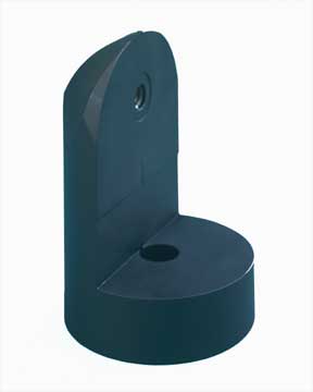
The Crown
The Crown, Part Number AN-CR is a small lightweight aluminum device that is designed to hold calibration equipment on very small Coordinate Measuring Machines. The overall height is four and one half inches (4.5", 114 mm). It has a three inch (3", 76 mm) diameter base, or foot. There is a counterbored hole in the center of the base that will accommodate either a three eighths of an inch or a ten millimeter socket head cap screw, to hold the Crown down on the C.M.M. table or other mounting devices.
The center line or pivot point of this device is three inches (76mm) above the base. If there are threaded holes in the C.M.M. table, the Crown can be screwed directly on to the table. This product is compatible with many of our C.M.M. mounting devices. It will screw directly to the top bulkhead of any of the "Anchor".

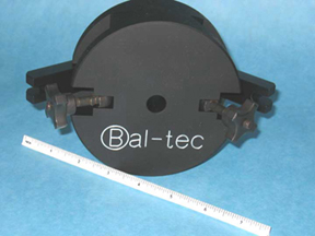
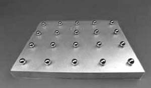
Ball Plate
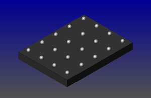
The 1216 Ball Plate is a simple, inexpensive and very versatile device for Coordinate Measuring Machine calibration and evaluation. The Ball Plate consists of a rather large rigid 12 inches (305 millimeters) by 16 inches (406 millimeters) plate that is 1.5 inch (38 millimeters) thick.
| Downloads | ||
|---|---|---|
| Solidworks | IGES | |
There are a series of 20 ultra precise 19 millimeter (.748 inch) diameter, hardened stainless-steel or aluminum oxide ceramic balls permanently mounted on the top face of the plate. To reduce the weight for ease of handling, the rear surface of the plate is relieved so that the complete plate weighs only 19 pounds (8.6 kg).
The very nature of a spherical geometry is unique in that it is the only form that has a single point that describes its exact position in three-dimensional space. The perfection of this point is only limited by the sphericity and surface quality of the ball. In addition to their having exceptional sphericity, the entire 20 ball set is carefully selected to be as exactly the same diameter as possible.
These ultra precise balls are spherical within less than 0.000005 inches (127 nanometers) and all 20 of the balls in the set are matched for size within 0.000005 inches (127 nanometers). These micro grain stainless-steel balls are hardened to 58 HRC minimum and thermo cycled to develop long term dimensional stability.
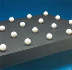
The aluminum plate can be black anodized and equipped with satin finished ceramic balls for optical applications. It is also available with ceramic balls. The real value of the Ball Plate over other artifacts is its ability to make a fast accurate every day or interim evaluation of the measuring machine's performance. The term value is used here, as a ratio of is performance to its cost. This cost is both its initial cost and the cost to use it in everyday operation. The large number of almost perfect sphere center to sphere center addresses tests all aspects of the C.M.M. system's performance, and it does it very quickly. Each of the 20 balls has an engraved number on the plate to identify it.
How can you avoid the very expensive laboratory calibration that is typically expected to be made on all calibration devices? What an interim or everyday evaluation is trying to achieve, is to make sure that all aspects of the machine are performing properly in between yearly calibrations. Immediately after the technician completes the annual machine calibration, place the Ball Plate on your machine and measure it. To be extra careful, rotate the Ball Plate 90 degrees and measure it again. For all practical purposes the spherical artifacts on the Ball Plate are themselves perfect. What you are doing by measuring their position on the Ball Plate is calibrating the Ball Plate within your machine's resolution. On this first measurement, the machine is calibrating the Ball Plate, and at the same time the Ball Plate is checking the machine.
When you are audited, you can point to your Ball Plate as the device used to evaluate the everyday or interim performance of this machine. Even when the question of traceability comes up, you have an unbroken documentation chain going back to the laboratory artifacts used by the technician for the machine's yearly calibration.
The Ball Plate is an excellent device for doing a complete yearly C.M.M. calibration; but when used in this mode, the Ball Plate itself requires a periodic laboratory calibration that is very expensive. At the very minimum, the exact three dimensional distance from the number one (#1.) master ball to each of the other balls on the plate must be mapped.
Doing the complete calibration of a C.M.M. by measuring the Ball Plate in the number of different positions required is quite time consuming, but extremely accurate. A rather elaborate on board software package is required to analyze this measurement data and to pinpoint the error sources, so that they can be manually corrected or software compensated.
See also: Three Dimension Ball Plate, 12" (30.48 cm) X 16" (40.64 cm ).
| Part # | Description | Price | Purchase |
|---|---|---|---|
| 1216 BALL PLATE | BALL PLATE, 12 X 16, PRECISE STEEL BALLS | $1980.00 | |
| 1216-SAT | BALL PLATE, 12 X 16, SATIN FINISHED BALLS | $1980.00 | |
| 3DBP12X16 | THREE DIMENSION BALL PLATE, 12" ( 30 CM ) X 16" ( 41 CM ) | $2750.00 | |
Three Dimensional Calibration Device 3D Ball Plate
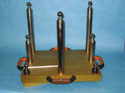
The three-dimensional, 3D, ball plate is one of the oldest calibration devices for the evaluation of Coordinate Measuring Machines. It dates back to the beginning of the commercial use of C.M.M.'s, where it was used with hard probes (conical cups) to evaluate the machines' overall performance. There are three mating pairs of precision ground and lapped cylinders that are rigidly mounted in three precision machined trenches in the bottom surface of the upper platform. These three pairs of cylinders form three Kinematic Vee Blocks. This upper platform containing the nine spherical masters can be removed and replaced any number of times, within less than one microradian.
Building a practical three dimensional (3-D, 3D) calibration artifact for modern Coordinate Measuring Machines is a tricky proposition. To be of any practical value, the artifact must be fairly large. It also must be rugged enough to be mechanically stable. This means that it must be able to withstand at least moderate handling and shipping abuse, but still be able to perform its task.
It must remain dimensionally stable over long periods of time. The materials used must not twist or turn. They must not grow or shrink with time. This job is accomplished by erecting a series of nine very rigid vertical posts, of different heights, from the surface of a stiff, flat pallet. The standard post heights are 12 inches (305 mm), 6 inches (152 mm) and 2 inches (51 mm).
On the top of each of the nine vertical posts is rigidly attached a very precise master sphere. For use on machines with touch trigger, or other mechanical probes, a one-inch (25.4 mm) diameter sphere is normally used. These spheres are made of a very high chrome, high carbon, Martensitic stainless-steel. This ultra fine grain material is hardened and thermal cycled to produce a minimum hardness of 58 HRC (Hardness on the Rockwell "C" scale). This special thermal cycle promotes long term dimensional stability.
All nine of the balls are precision lapped spherical and exactly same the diameter within five micro-inches (one hundred twenty five nanometers) tolerance. When the C.M.M. probe used is a non-contact laser scanner of other optical device, the balls used are usually a satin finished white ceramic material. The reduced surface quality of these satin finished balls limits the sphericity and common diameter to twenty-five micro-inches (0.63 micrometers). Balls made of many other materials, and diameters, can be supplied on special order. Satin finished steel and titanium are two of the more common.
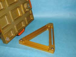
The rather large dimensions of the 3 D Ball plate, that are 12 inches (305 mm) by 16 inches (406 mm), requires an exceptional mounting method to avoid mechanical distortion. This is made more important, as any bending of the plate will cause serious first order errors in the spacing of the balls on the tops of the rather long posts. In order to gain perfect repeatability of all the elastic deflections, the platform of the 3 D Ball plate is Kinematically mounted.
The base for this kinematic mount consists of a triangular aluminum casting that is rigidly attached to the CMM table. Three high quality, hard Martensitic stainless-steel, spheres, are rigidly mounted at the corners of this triangle. The Kinematically mounted upper platform is equipped with two sets of isolated handles to facilitate placing it in position on the triangular platform, without any personal contact with the metrology elements.
Even though the 3-D Ball Plate is rather large and very rugged, it weighs only 30.5 pounds (13.84 kilograms). This is well below the 44-pound O.S.H.A. limit, to be handled by a single technician. The device can be custom built in other dimensional configurations. It can be configured with taller or shorter posts. It can also be built on a larger or smaller pallet. It can have a totally different aspect ratio, so that it is long and narrow.
| Part # | Description | Price | Purchase |
|---|---|---|---|
| 1216 BALL PLATE | BALL PLATE, 12 X 16, PRECISE STEEL BALLS | $1980.00 | |
| 1216-SAT | BALL PLATE, 12 X 16, SATIN FINISHED BALLS | $1980.00 | |
| 3DBP12X16 | THREE DIMENSION BALL PLATE, 12" ( 30 CM ) X 16" ( 41 CM ) | $2750.00 | |
See also the Standard 12X16 Ball Plate
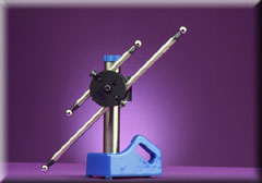
Dual Ball Bar Kit — Dual Ball Bar Kit Speeds C. M. M. Evaluation
This Device meets all of the ANSI requirements for "Performance Evaluation of Coordinate Measuring Machines", (CMM); according to B89.4.1-1997. The Ball Bar is an almost perfect C.M.M. artifact. It consists of two ultra precise spheres of exactly the same diameter that are securely attached to the opposite ends of a rather long rigid bar. By repositioning this simple gage a number of times, all of the potential errors of a C.M.M. can be evaluated.
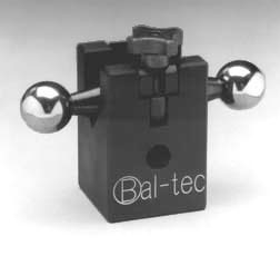
When used as a Monday Morning or interim check, it will quickly confirm the proper performance of the complete C.M.M. system. Any major malfunction of the machine can be identified by measuring the two Ball Bars in as few as four positions. The Kit consists of two Standard Ball Bars that are mounted above and below on a special clamping bracket. This bracket is rigidly fixed to a rugged 14 inch (355.6 mm) high stand. The two standard Ball Bars included in the kit have a sphere center to center length of 300 mm (11.8 inches) and 600 mm (23.6 inches).
Larger versions of the kit are available with a 24 inch (609.6 mm) high or a 36 inch (914.4 mm) high stand and Ball Bars as long as one meter (39.37 inches).
Ball Bar Stand and Kit Pricing
| Part # | Description | Price | Purchase |
|---|---|---|---|
| FS-10M | STAND TIE DOWN | $62.57 | |
| FS-14 | BALL BAR STAND 355.6 MM, 14 INCHES, INCLUDES A SINGLE CLAMP, COLLAR | $628.00 | |
| FS-14-0 | BALL BAR STAND ONLY, 355.6 MM, 14 INCHES | $381.00 | |
| FS-14-3-6 | BALL BAR KIT, INCLUDES 300 MM AND 600 MM BALL BARS, STAND, A COLLAR AND DUAL CLAMP | $1367.00 | |
| FS-1BB | SINGLE BALL BAR CLAMP | $151.00 | |
| FS-1BB-S | SMALL BALL BAR CLAMP | $151.00 | |
| FS-24 | BALL BAR STAND 609.6 MM, 24 INCHES, INCLUDES A SINGLE CLAMP, A COLLAR AND A TIE DOWN | $650.00 | |
| FS-24-0 | BALL BAR STAND ONLY, 609.6 MM, 24 INCHES | $401.00 | |
| FS-2BB | DUAL BALL BAR CLAMP | $180.00 | |
| FS-3 | TRI-MOUNT COLLAR, 2 INCH DIAMETER THROUGH HOLE, FOR HEAVY DUTY STAND | $273.00 | |
| FS-36 | BALL BAR STAND 914.4 MM, 36 INCHES, INCLUDES A SINGLE CLAMP, A COLLAR AND A TIE DOWN | $683.00 | |
| FS-36-0 | BALL BAR STAND ONLY, 914.4 MM, 36 INCHES | $488.00 | |
| FS-3BB | TRI-MOUNT COLLAR AND THREE SINGLE BALL BAR CLAMPS | $604.00 | |
| FS-WB | WASHER AND SHOULDER BOLT | $10.80 | |
The Invar® Ball Bar (Dumbbell)
A Ball Bar (Dumbbell) consists of two very precise spheres of exactly the same diameter securely attached to the opposite ends of a rather long rigid bar. Invar® Ball Bar (Dumbbell)s with their ultra low rate of thermal expansion have long been used in Coordinate Measuring Machine research, but until now they have been far too expensive for general use. The 36% Nickel steel alloy known as Invar® has a coefficient of thermal expansion of 0.68 microinches per inch per degree Fahrenheit. This is about one tenth that of steel and one twentieth that of aluminum. It is the lowest rate of thermal change of any commercially available metal. By purchasing the material in entire mill run volume and dedicating our company to serial production of Invar® Ball Bar (Dumbbell)s, we have brought the Invar® Ball Bar (Dumbbell) price down to a level for everyday use.
Important Note:
If the Ball Bar you need is 100 or 200 millimeters in length, you will need a small Ball Bar clamp to hold it. The distance between the balls on these Ball Bars will not clear the clamping fixture itself.
The actual change in length of a Ball Bar (Dumbbell) with a given variation in temperature is affected by three factors:
- The first factor is the Coefficient of Thermal Expansion of the material that the Ball Bar (Dumbbell) is made of.
- The second factor is the length of the BallBar being measured. The longer the Ball Bar (Dumbbell), the greater will be the change in length.
- The third factor is very subtle; but it is just as important as the other two. This is the speed at which a material exchanges heat with its environment. Aluminum exchanges heat very efficiently, so it changes dimension quickly. Invar®, on the other hand, does not exchange heat very efficiently at all, so it is very slow to move. This phase lag gives the calibration technician more time to perform the multitude of measurements required before even that very small changes in dimension actually take place. In addition, any short lived ups and downs, referred to as perturbations, in room temperature will be factored out entirely.
Using a Ball Bar (Dumbbell) with a low rate of thermal expansion is important, because such long dimensions are involved. Also, the long time period of well over an hour that is required to measure the Ball Bar (Dumbbell) in all of the 20 to 35 positions required to meet the ANSI-B89.4.1-1997 specifications for "Methods for Performance Evaluation of Coordinate Measuring Machines".
The Invar® Ball Bar price is $100.00 more than the standard steel Ball Bar.
Pricing for Precision Ball Bar, Invar®
| Part # | Description | Price | Purchase |
|---|---|---|---|
| PBB-INV-100 | BALL BAR, PRECISION, INVAR® 0100 MM, 3.937 INCHES | $473.00 | |
| PBB-INV-200 | BALL BAR, PRECISION, INVAR® 0200 MM, 7.874 INCHES | $517.00 | |
| PBB-INV-300 | BALL BAR, PRECISION, INVAR® 0300 MM, 11.8 INCHES | $523.00 | |
| PBB-INV-350 | BALL BAR, PRECISION, INVAR® 0350 MM, 13.779 INCHES | $523.00 | |
| PBB-INV-400 | BALL BAR, PRECISION, INVAR® 0400 MM, 15.748 INCHES | $535.00 | |
| PBB-INV-450 | BALL BAR, PRECISION, INVAR® 0450 MM, 17.7 INCHES | $535.00 | |
| PBB-INV-500 | BALL BAR, PRECISION, INVAR® 0500 MM, 19.685 INCHES | $538.00 | |
| PBB-INV-550 | BALL BAR, PRECISION, INVAR® 0550 MM, 21.653 INCHES | $538.00 | |
| PBB-INV-600 | BALL BAR, PRECISION, INVAR® 0600 MM, 23.622 INCHES | $547.00 | |
| PBB-INV-650 | BALL BAR, PRECISION, INVAR® 0650 MM, 25.59 INCHES | $547.00 | |
| PBB-INV-700 | BALL BAR, PRECISION, INVAR® 0700 MM, 27.559 INCHES | $551.00 | |
| PBB-INV-750 | BALL BAR, PRECISION, INVAR® 0750 MM, 29.528 INCHES | $551.00 | |
| PBB-INV-800 | BALL BAR, PRECISION, INVAR® 0800 MM, 31.496 INCHES | $628.00 | |
| PBB-INV-850 | BALL BAR, PRECISION, INVAR® 0850 MM, 33.464 INCHES | $580.00 | |
| PBB-INV-900 | BALL BAR, PRECISION, INVAR® 0900 MM, 35.433 INCHES | $580.00 | |
| PBB-INV-950 | BALL BAR, PRECISION, INVAR® 0950 MM, 37.401 INCHES | $594.00 | |
| PBB-INV-1000 | BALL BAR, PRECISION, INVAR® 1000 MM, 39.37 INCHES | $594.00 | |
| PBB-INV-1100 | BALL BAR, PRECISION, INVAR® 1100 MM, 43.307 INCHES | $594.00 | |
| PBB-INV-1600 | BALL BAR, PRECISION, INVAR® 1600 MM, 62.992 INCHES | $636.00 | |
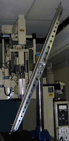
Giant Invar® Ball Bar (Dumbbell) — Evaluating Really Large Coordinate Measuring Machines with a Giant Invar® Ball Bar (Dumbbell)
The Ball Bar (Dumbbell) evaluation technique has been popular for over twenty years. The Ball Bar (Dumbbell) has always been a rather long rigid bar with two very precise spheres of exactly the same diameter firmly attached to the opposite ends, (see Standard Ball Bar.) This design works quite well on Ball Bar (Dumbbell)s up to about 900 mm (36 inches), but as they get longer, the Ball Bar (Dumbbell) is not rigid enough to resist bending due to the contact force of the measuring probe.
The first success in providing greater rigidity for longer Ball Bar (Dumbbell)s is the Way Out Ball Bar (Dumbbell) support system (see Wayout Ball Bar.) It uses a robust aluminum rail and auxiliary kinematically supported spheres to increase the stiffness of the Ball Bar (Dumbbell) five fold. The Way Out Ball Bar (Dumbbell) support system works well up to about one and one half meters (5 feet), but it becomes too cumbersome and too flexible after that. Development of a really good, long Ball Bar (Dumbbell) has taken a long time. The main difficulties have been that the Ball Bar (Dumbbell) must be rigid enough to provide good data, while still being light enough to be easily moved throughout the 20 to 35 positions outlined in the ANSI B89.4.1-1997 specifications for "Performance Evaluation of Coordinate Measuring Machines".
The chief obstacle to the development of long Ball Bar (Dumbbell)s was the industry's preoccupation with the definition of a Ball Bar (Dumbbell). By abandoning the old concept that a Ball Bar (Dumbbell) is two spheres attached to the ends of a single long bar, and redesigning it as a composite structure instead, the problem of building really long Ball Bar (Dumbbell)s has been solved. The break through design uses tubular Invar® members with their extremely low rate of thermal expansion, that is 0.68 microinches per inch per degree Fahrenheit, and a series of bulkheads to form a structural assembly. The thermal expansion of Invar® is about one tenth that of steel and one twentieth that of aluminum. Using this design, we end up with a very rigid structure that has a very low rate of thermal expansion; but is still light enough to be easily handled. Large one and one half inch (38 mm) diameter spheres are used on the Giant Ball Bar (Dumbbell). This greatly facilitates the probing of the target sphere from the long distance that separates it from the operator. Two inch (51 mm) diameter hollow spheres are offered as an option that enhances the ease of probing even more.
By kinematically supporting this tubular structure at the end bulkheads, it may be moved through a wide array of horizontal, vertical and angular positions with a minimum of distortion. The problem of physically positioning these large structural devices is accomplished by supporting the Giant Ball Bar (Dumbbell) on two tubular framed Invar® tripods, (see Giant Metrology Tripods). The thermal stability of the Invar® construction of these tripods is important because they become part of the actual measurement during each evaluation.
For giant Ball Bar (Dumbbell)s up to eight feet (2.5 meters) long, we have developed an economical light weight system that only uses a single tripod. Ask for the Single Tripod Giant Ball Bar (Dumbbell) System.
| Part # | Description | Price | Purchase |
|---|---|---|---|
| GBB | GIANT BALL BAR | $2101.00 | |
| TRI | TRIPOD FOR GIANT BALL BAR | $2090.00 | |
| GBB-TRI | GIANT BALL BAR WITH TRIPOD | $4191.00 | |
Giant Metrology Tripods
Evaluating Really Large Coordinate Measuring Machines with a Giant Invar® Ball Bar (Dumbbell)
Part Number: GBB-TRI: Up until now, there have been two forms of Metrology Tripods available. There is a huge lumbering steel one that is very rigid but can only be moved on rollers. There is no way to compact this giant one for storage. Then, there is the portable one that is made of lightweight but high expansion aluminum. It can be quickly folded up and carried away, but it is neither rigid nor dimensionally stable.
The alternate to these is a tubular Invar® tripod that is very dimensionally stable, reasonably portable, and is made rigid through design not brute mass. The tubular Invar® has the extremely low rate of thermal expansion of .68 micro inches (.017 micrometers) per inch per degree F. which makes this tripod impervious to nominal temperature changes. The expansion of this material is one twentieth that of aluminum and one tenth that of steel.
The all in line construction of this Tubular Invar® Metrology Tripod gives it unparalleled stability. Although its design is somewhat more intricate, than standard tripods, this design increases the stiffness by a full order of magnitude compared with the conventional out board construction. The upper ends of the six, three quarter inch (19mm) diameter Invar¨ tubes, that form the tripods legs, are rigidly glued into deep counterbores in the one and one quarter inch (31 mm) diameter hardened and lapped steel spheres. These hardened and precision lapped steel spheres are clamped, under tension, into matching spherical seats in the bottom (not on the side, as with conventional designs) of the rugged one and one half inch (38 mm) thick upper bulkhead. The lower ends of these six tubes are rigidly glued into three rugged steel blocks that form the upper end of the foot assemblies.
The lower ends of these steel blocks terminate in one and one quarter inch (3l mm) diameter hardened and lapped steel spheres. These spheres have a deep; three eighths of an inch (9.5 mm) threaded hole that is used to clamp them in solid contact with the mating spherical seats in the rugged steel blocks. These are the same blocks that terminate the tubular Invar® legs. The bottom of these large diameter hardened steel spheres locate in matching spherical seats of the rugged two inch (5 l mm) diameter feet of the Tripod.
The rugged one and one half (38 mm) thick top bulkhead can be configured to hold any instrument package. This adaptation may range from kinematic couplings to hold a Giant Ball Bar (Dumbbell) to male threads to hold an Optical Level, a Jig Transit or a Theodolite.
The top bulkhead is 48 inches (1.2 meters) above the floor. The footprint of this tripod is a giant 60-inch (1.5 meters) diameter. This large circle provides excellent mechanical stability. The lower bulkhead and horizontal support structure is only slightly above the three feet to provide the maximum stiffness. The lower bulkhead provides an additional platform for location and support of a measuring machine or calibration devices. The strict in line design of the three legs and the lower horizontal support mechanism provides three distinct pockets that allow up close operation of instruments that are attached to the rugged bulkheads.
The mechanical rigidly and temperature stability of the Tripod are extremely important, because the Tripod becomes an integral part of the instrument package mounted on it. A reasonably low weight for the Tripod is important, so that a single technician can do any repositioning required. This complete Tripod weighs in at under 40 pounds (18 kg). The full operation of this Tripod requires no hand tools of any kind. There will be no time lost, looking for missing wrenches.
This Invar® Tripod will fold up for easy transport and compact storage. To fold up the Tripod, first remove the three hex hand knobs at the bottom that secure the legs to the horizontal struts. Now remove the three horizontal Invar® struts by unscrewing them using the large hex hand knob attached to each. Next, remove the three special plastic knobs that are screwed into the bottom surface of the upper bulkhead. Now replace them by screwing the horizontal struts in their place. These three special knobs are then used to secure the three legs of the Tripod to the side of the lower bulkhead. After folding the Tripod, the 40 pound (18 kg) device can be carried away by the center support strut.
There is a carrying handle available as an accessory. This handle, Part Number H-40, clamps onto the center Tubular Invar® strut for easier transport. There is a secondary platform, Part Number PLT-96, available as an accessory. With this platform the overall height of the Tripod is adjustable from 50 inches (1.3 meters) all the way up to 8 feet (2.5 meters).
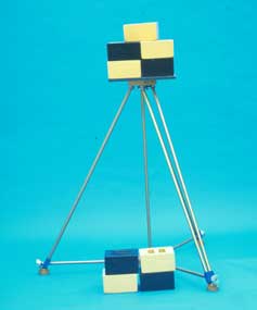
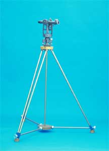
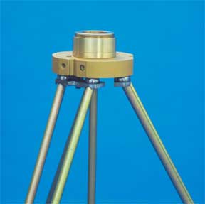
| Part # | Description | Price | Purchase |
|---|---|---|---|
| GBB | GIANT BALL BAR | $2101.00 | |
| TRI | TRIPOD FOR GIANT BALL BAR | $2090.00 | |
| GBB-TRI | GIANT BALL BAR WITH TRIPOD | $4191.00 | |
Long Ball Bar (Dumbbell) Bend
There is a trend today for companies to purchase larger and larger Coordinate Measuring Machines (CMMs). Today’s parts tend to be larger and more complicated as former subassemblies are being merged together into a single monolith in the interest of reduced cost. The cost of larger coordinate measuring machines is lower than ever before. A larger machine only requires a larger frame and longer scales, all of the expensive stuff is already there on a smaller machine.
A Ball Bar (Dumbbell) is the most accurate and least expensive evaluation and calibration device for coordinate measuring machines. As the Ball Bar (Dumbbell) gets longer to facilitate the evaluation of these larger coordinate measuring machines, there are two primary problems that occur. The length change of the Ball Bar (Dumbbell) due to temperature becomes extreme and the sag due to the movement of the Ball Bar (Dumbbell) from vertical to horizontal, that must occur, in order to evaluate the machine errors, can cause a large change in the Ball Bar (Dumbbell) length.
Carbon Fiber and Invar Ball Bars
In order to minimize the temperature effects on the Ball Bar (Dumbbell), it must be constructed from a material with a very low rate of temperature sensitivity. From a practical cost perspective, the two material options are Invar® and Carbon Fiber composites. The three things that influence the bending of the Bar are the stiffness or Young’s modulus of the material, the diameter of the Bar, and the weight of the material.
At first look, carbon fiber composite seems like a good choice, but in the real world the apparent advantages disappear quickly. In theory, carbon composites materials have a 50,000,000 pound per square inch Young's Modulus of elasticity (stiffness). That is the stiffness of the carbon whiskers, by the time the fiber is mixed with the plastic binder, it only ends up a small fraction of that. The stiffest cylindrical tube that we have ever measured in our metallurgy lab is only 15,000,000 pounds per square inch, and most are much lower.
Carbon fiber composite material is very hygroscopic . This means that it changes length dramatically with changes in the moisture of the surrounding environment. Finally, this material in the relatively large diameter that it must be used in Ball Bar (Dumbbell) applications is very expensive. Having said all of this, if the customer insists, we will custom make Carbon Composite Ball Bars (Dumbbells) of the highest quality, at the most economical price.
The second and by far the most practical approach is to construct the long Ball Bar from Invar®. This material has almost no expansion or contraction due to temperature. The Young’s modulus of elasticity for Invar® is 20,000,000 pounds per square inch. This material is quite expensive, but by keeping the dimensional cross section to three quarters of an inch diameter (¾”, 0.75”, 19.05 mm) with an 0.062 inch (1.57 mm) wall thickness the cost of even a long Ball Bar (Dumbbell) is modest.
The Cantilever Ball Bar© design with the Way Out Ball Bar Support© is a well established, time proven design. When a Ball Bar (Dumbbell) gets to be one and one half meter (60 inches) long, or even one meter (40.00 inches) the bar itself will have considerable sag. This sag shows up when it is held horizontal. To cope with this problem, we have experimented with a wide variety of sophisticated, adjustable kinematically correct devices, until the reality of the situation showed us the one best and simplest solution.
Sagmiser©
The Sagmiser© is that solution, it consists of one or more small flat tables that are adjusted to the proper height to provide sag compensating support for the Ball Bar tube. With this simple inexpensive device, mechanical sag becomes an insignificant factor with the use of the Ball Bar. To appreciate this situation fully, it should be remembered that the balls are situated on the neutral bending plane, so the minor sag that does still occur is a second order error of very limited consequence.
The Mammoth, A Super Heavy Duty Gage Stand
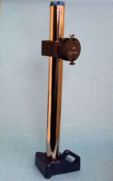
The Mammoth Gage stand is designed as the universal foundation for a broad array of metrology applications. It can be used as a heavy duty stand to hold Ball Bars (Dumbbells) and other calibration devices during Coordinate Measuring Machine or machine tool evaluation. The Mammoth can be held in an absolutely fixed position, on a machine table, by simply tightening the hand knob on top of the Mammoth's three-inch diameter post. The Mammoth Gage Stand combines a very large foot print with an extremely rugged 30 pound (13 kg) cast iron base and a giant three inch (76 mm) diameter vertical column to create a new level of rigidity and stability in a portable gage stand. The three-inch (76 mm) diameter vertical column is precision ground and hard coated.
Three large three-quarter inch (19mm) diameter feet are rigidly screwed and glued to the bottom surface of the rugged cast iron base. These three feet are hardened stainless-steel that are precision ground and lapped flat and coplanar to provide the greatest mechanical stability possible. For added versatility, a precision dovetail is machined into the front surface of the cast iron base. This wide shallow dovetail can be used to hold accessories such as a straight edge for making very accurate squareness measurements. This same dovetail will hold a rugged plate with two feet attached to support the Mammoth when it is laid down for horizontal measuring applications.
The Mammoth can be used to hold a pair of 60-degree centers for measuring the concentricity and roundness of shafts on center. There is a three-eighths inch diameter (0.375", 3/8", 9.52mm) threaded hole machined in each side of the cast iron base that can serve to tie The Mammoth can be used as an indicating comparator gage. There is a three quarters of an inch diameter (0.75", 3/4", 19.05mm) national fine threaded hole in the top center of the cast iron base that serves as a fine adjusting screw to set an indicator to zero when the stand is used as a comparator gage.
The Mammoth gage stand makes an excellent indicating height transfer gage that will move smoothly over a surface plate. The three precision, flat lapped feet provide a kinematic reference plane that actually provide micro inch (sub micrometer) measuring capability. Many of the standard components developed for use in C.M.M. fixture building and modular gaging applications can be adopted for use with the Mammoth gage stand. These combinations will economically solve many unique gaging problems.
The Mammoth Gage Stand is 36" (914 mm) tall. Special sizes will be quoted on request.
Mammoth Pricing
| Part # | Description | Price | Purchase |
|---|---|---|---|
| MAMMOTH-0 | BALL BAR STAND ONLY, HEAVY WEIGHT, 914.4 MM, 36 INCHES | $543.00 | |
| MAMMOTH | BALL BAR STAND, HEAVY WEIGHT, 914.4 MM, 36 INCHES, INCLUDES A SINGLE CLAMP, A COLLAR AND A TIE DOWN | $955.00 | |
Complex CMM Probes Characterized with Mini Ball Bar
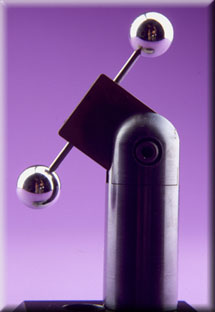
The contact probing system of a Coordinate Measuring Machine is characterized by evaluating a large number of measurements on the surface of a very precise sphere of known diameter. This precise sphere must be rigidly supported and held in a fixed position during the probe characterization process, otherwise misleading data will be collected. This rigid support unavoidably covers up part of the spherical surface, which is therefore hidden from measurement by the contact probe. This hidden area is of no consequence when working with vertical probes, but it is of prime importance when the probe is inclined, horizontal or of compound, i.e. star design.
The simple solution to this problem is to use the Ball Bar (Dumbbell) concept as developed many years ago. This device uses two very precise spheres of exactly the same known diameter which are securely mounted on opposite ends of a rigid bar. This hidden area on the first sphere is exactly 180 degrees from the hidden area on the second, so 100% of the spherical surfaces are in effect available for probing.
The distance between the centers of the two spheres is absolutely constant. In effect, a measurement made on one sphere is exactly the same as a measurement made on the opposite sphere minus the fixed distance between the two centers. The Mini Ball Bar (Dumbbell) is a versatile version of this device. It is offered in four standard spherical diameters - 1.00 inch (25.4 mm ) Part #MBB-100, .750 inch (19.05mm) MBB-75, 0.500 inch (12.7mm) MBB-50, and 10mm (0.3937 inch) MBB-39. Custom diameter spheres or combinations of two different spheres on the same Ball Bar (Dumbbell) will be quickly supplied at reasonable cost.
The Ultra-Precise Calibration spheres on the three larger diameter versions are produced from very fine-grained, high chrome, high carbon, stainless-steel. They are hardened to 58 Rockwell C for wear resistance and ultra cold cycled for long term dimensional stability. The 10 mm (0.3937 inch) sphere is made from micro grain tungsten carbide. It is dimensionally stable, very corrosion resistant, and it is much more rigid and wear resistant than steel.
The 1/8 inch (0.125", 3.175mm) diameter shaft used to mount the two ultra-precise spheres is made of tungsten carbide. Because this very rigid material allows such a small diameter shaft to be employed, the maximum area of the spherical surface is exposed for measurement. It would require a steel shaft of .408 inch (10.36mm) diameter to match its rigidity.
The incline position of the Mini Ball Bar (Dumbbell) is adjustable through a broad angular range. In this way, the ideal position to match each probe configuration can be used. The bar can be quickly switched to the opposite side of the post so that compound, i.e. star probes can be accommodated without relocating the base. The 1-1/4 inch(1.25", 31.75mm) diameter by 4 inch (101.6mm) high rugged steel post has an M10 X 1.5 threaded hole in its base to fasten it to a mating surface.
A three inch (76.2mm) long by 1-1/4 inch (31.75mm) diameter extension post (Part# P-EP-3) and a 6" inch long extension post (Part # P-EP-6) are available to raise the height of the Mini Ball Bar (Dumbbell) when characterizing star probes with long vertical members. The rugged steel post that carries the Mini Ball Bar (Dumbbell) is coupled to the C.M.M. table through a robust steel platform (Part# PLT-4) (see Technical Data Sheet CMM-6.A.). This platform is four inches (101.6mm) diameter by 1-1/2 inch (38.1mm) thick and weighs over five pounds (2.27kg). The bottom of this platform is machined to leave an annular ring around the outside. This ring is precision lapped flat to provide a very stable connection with the top of the C.M.M. table. An M10 x1.5 threaded hole through the center of the platform allows the post to be securely clamped to the platform.
Another accessory available for use with the Mini Ball Bar (Dumbbell) is the 45 degree Angle Block (Part# BLK-45) which is used to incline the sphere and post at an angle for easier access. In order to facilitate the connection and removal of the posts and extensions, a 3/16 inch (4.76mm) diameter clearance hole through the parts is provided. A removable steel pin made of high-tensile stainless-steel is supplied as a handle. An attractive black oxide finish is applied to the post and other accessories to help prevent corrosion.
Mini Ball Bar Pricing
| Part # | Description | Price | Purchase |
|---|---|---|---|
| MBB-39 | MINI BALL BAR, 10 MM, 0.3937 INCHES | $498.00 | |
| MBB-50 | MINI BALL BAR, 12.7 MM, 0.5 INCHES | $498.00 | |
| MBB-75 | MINI BALL BAR, 19.05 MM, 0.75 INCHES | $498.00 | |
| MBB-100 | MINI BALL BAR, 25.4 MM, 1 INCHES | $498.00 | |
A Novel Ball Bar (Dumbbell) Stand for Quicker CMM Evaluation
Part Numbers QG-14, QG-24 & QG-36: IT'S FAST - Just squeeze the Quick-Grip handle with your right hand, and you can zip the two ball kinematic coupling up or down the rugged two-inch diameter hard surfaced column. At the same time, your left hand can propel the base around the table through a conveniently located handle. Nothing to tighten, nothing to loosen, no screws, no tools, just squeeze the grip; and in three seconds, the Ball Bar (Dumbbell) is in a new position and ready to measure again.
The conventional technique for supporting the Ball Bar (Dumbbell) while evaluating a Coordinate Measuring Machine is to hold the Ball Bar by its center on a stand consisting of a vertical post fixed to a base. This is the Free Standing Ball Bar (Dumbbell) technique. The accuracy of the Free Standing Ball Bar (Dumbbell) is plagued by a serious shortcoming. The problem is that the contact force of the measuring probe bends the Ball Bar (Dumbbell) a small amount but deflects the vertical post of the stand a large amount. This large deflection of the post results because the force of the measuring probe is multiplied many times by the lever action of the long, unsupported sections of the Ball Bar (Dumbbell). These bending and deflection moments vary with the location of the hit by the probe on the spheres. The greatest deflection occurs perpendicular to the axis of the Ball Bar (Dumbbell) and the deflection is almost zero on the very ends of the spheres. The result of this error is diabolically severe. Instead of a simple second order or cosine error as might be expected, there is a combination of first and second order errors. Because of the uneven deflection of the Ball Bar (Dumbbell), the spherical fit algorithm of the CMM's computer sees the spheres as much smaller in diameter. A large first order error results when the CMM uses this bad data to determine the center to center distance between the spheres. This error is doubled because each end of the bar is deflected.
Finally, this combination of errors is added to the two second order cosine errors caused by the actual bending of the bar itself to become a sizable error indeed. By combining the Three Ball Kinematic Platform on the CMM table with a Two Ball Kinematic Coupling on the Quick-Grip Stand and the Ultra-Precise Ball Bar (Dumbbell) with its precision lapped cylinders, a day's work can now be done in 20 minutes.
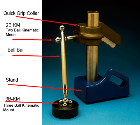
The Two Ball Kinematic Coupling gives remarkable two axis self-alignment. Its ability to track the cylinder as the coupling moves up and down the post is quite obvious. What is less obvious is that this coupling can be rotated 30 or more degrees in either direction and still render the same microinch accuracy. The 0.750 inch (19.05mm) diameter precision balls used in both of the kinematic devices are ultra fine-grained stainless-steel which is hardened to 58 HRC for wear resistance. These balls may be rotated to many different positions, thus giving years of quality use.
In addition to the ultra-fast positioning capability of the Quick Grip Stand, it all but eliminates the main error associated with Ball Bar (Dumbbell) evaluation. This error is a deflection of the target ball caused by a bending and deflection of the Ball Bar (Dumbbell) and the vertical support post by the contact force of the measuring probe. It eliminates the problem by supporting both ends of the Ball Bar (Dumbbell) by very rigid structures which eliminate the bending and twisting movements.
A very accurately-lapped cylinder that is both straight and round within 2.5 micro-inches (63.5nm) is provided at each end of the Ultra-Precise Ball Bar (Dumbbell)s. This cylindrical area at the end of the Ball Bar (Dumbbell) is cradled in a yoke formed by the two precision spheres of the Two Ball Kinematic Coupling (Part Number 2B-KM; see Technical Data Sheet CMM-3). This two ball kinematic coupling rigidly supports the Ball Bar (Dumbbell) against deflections due to probe contact force, while allowing complete freedom of movement and perfect self-alignment with the stand. In addition to the obvious cradle formed when the two ball coupling is at right angles to the cylinder, the coupling can also by rotated over 30 degrees in either direction and still render the same micro inch accuracy. The end result is an extremely rigid coupling system that introduces absolutely no distortion due to clamping or over-constraint.
Ball Bar (Dumbbell)s have very long dimensions and are extremely sensitive to temperature. The main source of temperature change occurs through hand-contact by the machine operator. Once the Ball Bar (Dumbbell) is located in the kinematic coupling, there is almost no reason for the operator to handle it again. The Design uses unique high strength connections to join the Ultra Precise Spheres to the bar. Computer controlled Electrical Discharge Machines (EDM) are used to drill small diameter concentric holes deep into the already finished spheres. This process uses millions of tiny bursts of electrical energy to erode a hole in each sphere without affecting their original high quality. Both ends of the bar have corresponding drilled holes. As the high-strength glue is applied to the assembly, a steel pin is inserted between these holes to form very strong connections.
In order to provide a stiff, light-weight Ball Bar (Dumbbell) that is still very rigid, the bar is made of 3/4 inch (19.05mm ) diameter steel tubing that has been cold drawn over a mandrell. This steel tubing is electroless-nickel-plated to provide an attractive appearance and to give excellent corrosion resistance. Because any long gage device is extremely sensitive to increases in temperature through contact with the person operating the measuring machine, a special thermal isolation is provided for the Ultra-Precise Ball Bar (Dumbbell). This is not just bulky insulation, but a series of insulation, isolation and then insulation again. This protects the Ball Bar from dramatic increases in length which would normally be caused by brief contacts with the human operator.
The 25 lb. (11.34 Kg) solid cast iron base of the stand is fitted with three hardened steel feet that are precision lapped flat and coplanar to provide a microinch stable reference surface. A heavy-interference fit permanently fixes the robust 2 inch ( 50.8mm ) diameter hard clad post in the solid cast iron base. The Quick-Grip Stand is supplied with a hold-down device that consists of a long, threaded shaft which extends all the way down through the length of the vertical column and screws into the CMM table, thus removing even the smallest tendency of the stand to tip when making extremely critical evaluations. When ordering, please specify the size and thread count to match the threads in the table of your Coordinate Measuring Machine. A tether, consisting of a plastic-covered steel cable, is provided with the two ball kinematic coupling. It goes around the upper end of the Ball Bar (Dumbbell) to prevent an accidental fall of the bar in case of a crash.
The Quick Grip stand is available in three standard heights:
- Part Number QG-14 is 14 inches (355.6mm )
- Part Number QG-24 is 24 inches (609.6mm )
- Part Number QG-36 is 36 inches (914.4mm )
| Part # | Imperial Size | Metric Size | Description | Price | Purchase |
|---|---|---|---|---|---|
| QG-1 | QUICK GRIP WITHOUT STAND | $303.00 | |
||
| QG-24 | 24" | 609.6 mm | QUICK GRIP, 609.6 MM, 24 INCHES, STAND, 2B-KM AND 3B-KM ( TWO AND THREE BALL KINEMATIC MOUNT ) | $831.00 | |
| QG-36 | 36" | 914.4 mm | QUICK GRIP, 914.4 MM, 36 INCHES, STAND, 2B-KM AND 3B-KM ( TWO AND THREE BALL KINEMATIC MOUNT ) | $769.00 | |
| QG-14-0 | 14" | 355.6 mm | 14 INCH QUICK GRIP STAND | $453.00 | |
| QG-24-0 | 24" | 609.6 mm | 24 INCH QUICK GRIP STAND | $467.00 | |
The Ball Bar (Dumbbell) Ranger
Technical Data Sheet: CMM-19
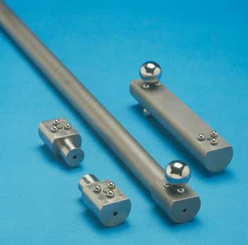
The Ball Bar (Dumbbell) Ranger performs exactly the same function as a standard Ball Bar (Dumbbell) for Laser Trackers and Portable Coordinate Measuring Machines. It will also act as a traceable calibration device for telescoping Ball Bar (Dumbbell)s.
The Ranger consists of two extremely accurate Three Ball Kinematic Coupling made of Invar® that are supported a fixed distance apart by a rigid Invar® tube. When this absolutely fixed distance between the Kinematic Couplings is measured in the 20 to 35 positions specified by the ANSI B89.4.1-1997 standard, a full evaluation of the Laser Tracker or Portable C.M.M. is made.
For Laser Tracker evaluation, the position of the target reflector is measured with the sphere of the reflector accurately located in one of the nests provided by the three spherical contacts of the first Kinematic Coupling. The target reflector is measured again after being moved to nest in the second Kinematic Coupling and the distance between the two positions is calculated. Some Laser Trackers are capable of moving between two target reflectors and calculating their position without tracking the sphere from one position to the other. If this technique is used, the two reflectors should be a carefully matched set.
Powerful rare earth magnets are used to attract the optical target sphere firmly into the center of the Kinematic Coupling. When evaluating Portable C.M.M.'s, a 1/2 inch (12.7mm) or a 15mm (.6 inch) diameter test probe sphere is attached to the measuring head. This 1/2 inch (12.7mm) or a 15mm (.6 inch) sphere is then seated in each of the two Three Ball Kinematic Couplings and the length between them is calculated.
The Ranger is subsequently repositioned and measured in each of the 20 to 35 ANSI orientations. The Ranger is supplied in two standard configurations. In the first configuration, the Three Ball Kinematic Coupling is built for 1/2 inch (12.7mm) diameter spheres, and in the second, they are arranged for 1 1/2 inch (38.1mm) diameter spheres. The standard sphere center lengths available are as follows.
Laser Tracker Calibration Device — Articulating Arm Calibration Device — Portable Arm Calibration Device — Giant Ball Bar Like Calibration Devices — Unistraint
Unistraint is a very unique concept, in long calibration artifacts (patents applied for). This concept is based on simple principals of physics. All of the falldarall about the original camber or waviness of the artifact and all of the smoke screen of stiffness to weight ratios, become poppy cock.
The difference with Unistrain is that it is not based on constraint or for that matter over constraint but on the simple principal that “if it doesn’t bend it doesn’t matter.” We call the new doctrine Unistraint.
The basic design is based on the resistance of very thick sections of material to bending. In the case of Unistraint its, the resistance of four huge, sixteen inch thick sections of aluminum to bend, from the minor load imparted by change in the force of gravity, when the Ball Bar like structure, is moved from vertical to Horizontal, and of course any intrem position.
The fact that the sixteen inch thick sections are only 0.020 inches thick has very little effect on the bending moment generated. This brings us back to the original premise that “if it doesn’t bend it doesn’t matter.” There has always been, serious problems with slippage in the rotary position of large calibration artifacts, during use. This dilemma has been entirely eliminated, through the application of two gear tooth like “Hirth plates” that form a preloaded coupling, which both locates the artifact at a very accurate incline and also lock it there without even microinches of movement.
We are building these Giant calibration artifacts in two, off the shelf, standard lengths. There is the really giant two point three meter (90.5512”) long version, that is part number US 2.3-B (for Ball Bar version) and US 2.3 TH (for Laser Tracker version) and there is a shorter fifty inch (1,270mm) long version, part number US 2.3-B (for Ball Bar version) and US 2.3 TH (for Laser Tracker version).
One of the two standard designs is a simple standard “Ball Bar.” The body of this Ball Bar is invar with its almost zero rate of thermal expansion and contraction and unlike carbon and glass fiber composites it has absolutely zero sensitivity to moisture. This Ball Bar is equipped with one inch diameter balls of either hard stainless-steel or Zirconium oxide ceramic.
The second, standard, off the shelf configuration has the same general construction but with a magnetically preloaded trihedral nest, on each end, to hold a Spherical Retro reflector (SMR), for use in calibrating Laser Trackers. This standard configuration is setup for, one and one half inch diameter spherical retro reflectors, but we can also supply a version that is compatible with seven eights of an inch or one half inch diameter, SMR’s.
A super bonus with the design of the Unistraint Ball Bar is that the version used to calibrate Laser Trackers can be converted to a standard Ball Bar by just screwing accessory ball bar ends, Part Number ABB-1 into the trihedral mounts. The feature that entirely eliminates the influence of the original gerometry of the artifact is that the invar bar that forms the body of the Ball Bar or trihedral nest, is encapsulated in a high stiffness foam 25000 P.S.I. that connects all elements of the artifact together to form a pseudo monolithic structure.
Pricing
| Part Number | Description | Price |
|---|---|---|
| US-48-B | $3000.00 | |
| US-2.3-B | $3400.00 | |
| US-2.3-LT | ||
| US-48-LT |
The Centerline Ranger
Another version of the Ranger places the balls on the centerline of the bar which is the neutral bending plane of the Ball Bar. Any bending will have a very small effect on the length of the Ball Bar, because all of the errors will be cosine and second order errors. This calibration artifact is also known as a "Laser Scale Bar." To eliminate bending on longer Ball Bars, the Wayout Ball Bar Support Rail is used in conjunction with the 1 1/4" (1.25", 31.75 mm ) support balls on the bar fixed near the Ball Bar ends.

One breakthrough after another has brought Laser Tracker Calibration to an accurate, economical science. These new developments have so improved the science of Laser Tracker calibration that the level of quality is now entirely compatible with the well tested ANSI-B89.4.1-1997 standard for Coordinate Measuring Machine (CMM ) evaluation. These developments give Laser Tracker Calibration a legal and a traceable foundation, and it can all be done on the shop floor. The calibration can also be done economically. Our Giant Invar® Ball Bar is widely used by the equipment manufacturers for calibrating laser trackers, but it is huge and expensive; and it really isn’t required to do an adequate job of calibration.
In addition to providing a complete calibration device for all laser trackers, this same exact artifact and mounting system will accurately calibrate portable C.M.M.’s, optical scanners, optical probes and the various other devices in current use and still on the drawing boards. This device can also be adapted as a scale bar by calibrating the inter sphere length (refer to N.I.S.T. ). To facilitate the calibration of optical devices, a pair of satin finished titanium balls is available with a high magnetic permeability button installed. These satin finished titanium balls are substituted for the Spherically Mounted Retro-reflector (SMR’s) in the magnetically preloaded three ball kinematic nests mounted on each end of the “New Centerline Ball Bar Ranger”. These satin finished titanium balls are the ideal artifact for calibrating optical systems. Unlike satin finished ceramic, they give a single image. These balls have no spectral reflectivity or hot spots.
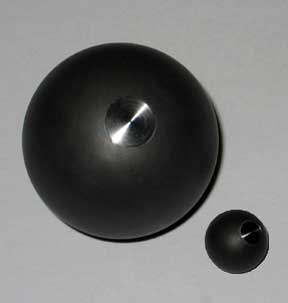
The balls are made in the three standard SMR diameters:
| Part Number | Description | Price |
|---|---|---|
| SFTB-PERM-.5 | One half inch (1/2”, 0.5”, 12.7mm ) diameter | $59.56 |
| SFTB-PERM-.875 | Seven eighths inch (7/8”, 0.875”, 22.2 mm ) diameter | $65.85 |
| SFTB-PERM-1.5 | One and one half inch (1 ½”, 1.5”, 38.1 mm ) diameter | $457.00 |
This new approach to Ball Bar technology uses the same age old principle that the distance between the two balls of a Ball Bar will remain “exactly” the same, no matter what the geometric location of the Ball Bar is. With this absolute knowledge, the actual performance of a Laser Tracker can be determined right out in the field.
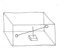
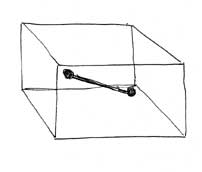
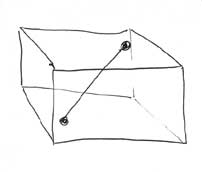
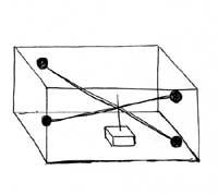
A standard Ball Bar (Dumbbell ) consists of two very precise balls permanently attached to the ends of a long rigid bar. Using a Standard Ball Bar is not at all practical for use with Laser Trackers. The solution for this difficulty is to use the “New Centerline Ball Bar Ranger”, instead of a conventional Ball Bar. What the “New Centerline Ball Bar Ranger” does is to substitute a magnetically preloaded three ball kinematic nest for each of the two balls. When two SMR’s, are placed in the two magnetically preloaded three ball Kinematic nests, the distance between these two SMR’s, forms the equivalent of a Ball Bar. Ideally the SMR’s used would be one half inch (12.7mm) diameter to limit the weight and to make the device compatible with portable CMM calibration, however seven eighths of an inch (7/8”, 0.875”, 22.2 mm ) diameter and one and one half inch (1½”, 1.5”, 38.1 mm ) diameter versions are also available.
The “Centerline Ball Bar Ranger” is actually a revision of a fifteen year old product. A very important change from the old version of the Ball Bar Ranger puts the SMR’s right on the neutral bending plane of the Ball Bar. This dramatic improvement reduces the effect of any sag or bending of the bar, to an infinitesimal second order cosine error. If the centerline between the two SMR’s are above or below the neutral bending plane of the bar, any bending error becomes a huge first order error. The further above or below center the SMR’s are placed, the greater the error will be.
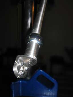
In operation, the Laser Tracker is allowed to zero in on the SMR on one end of the “Centerline Ball Bar Ranger”. Next, the Laser tracker is directed to the SMR on the other end of the “Centerline Ball Bar Ranger” and the distance between them is recorded.
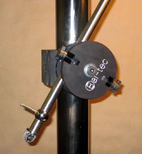
An alternative that must be used on older trackers is to zero in on the SMR where it is located in one of the three ball kinematic couples. The SMR is then moved while the laser tracks it to the three ball kinematic couple at the other end of the “Centerline Ball Bar Ranger,” and the distance is recorded. What may not be obvious is the very complex set of variables that the multiple positions of the single dimension of the “Centerline Ball Bar Ranger” presents to the mechanism and the software of the laser tracker.
Next, the “Centerline Ball Bar Ranger” is moved to a new geometric location and the two measurements are repeated (as outlined by the ANSI B89.4.1 specification.). To make a full machine evaluation requires 21 of these positions, but just a few of these measurements will give you a good interim evaluation of your Laser Tracker’s performance.
In addition to its use as a volumetric evaluation tool, (which does not require any length calibration) the “900 mm Centerline Ball Bar Ranger” can have the actual ball center to ball center dimension between the two, three ball kinematic couplings accurately calibrated. This is done by placing two master balls of the proper diameter in the magnetically preloaded three ball kinematic nests and then measuring the distance between their centers. With this extra data, you can reach a new level of assurance for your machine’s performance. Typical cost for this ball center to ball center calibration is $150.00 per Ball Bar Ranger.
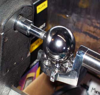
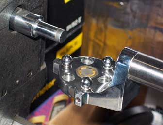
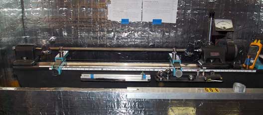
The “Centerline Ball Bar Ranger” used for calibration of Laser Trackers are typically 900 mm (35.5 inches ) or one and one half meters 1500 mm (59 inches ) long or 2300 mm (90.55 inches) long. These rather lengthy “Centerline Ball Bar Rangers” actually require two forms of support to stop the bending of these long Ball Bars when they are moved to different positions during the calibration. The “Centerline Ball Bar Ranger” is kinematically supported at each end by an auxiliary support ball; this device is called the Cantilever Ball Bar Support.
To support the cantilever version of the “Centerline Ball Bar Ranger” and to provide a method to connect it to our Tri-Mount collar on the three inch diameter post of our Anchor, a contoured aluminum rail, called the Way Out Ball Bar Support is available. Wayout support rails, that are 900 mm and longer are equipped with our “Sagmiser”™ system that eliminates gravity induced bending of the Ball Bar. For a full description of our Tri-Mount Collar and Anchor system. This contoured rail is five times as rigid as the Ball Bar itself.
It is also important that the “Centerline Ball Bar Ranger” be mounted on the Wayout Ball Bar Support and to be held rigidly in position during the measurements. The ideal supporting device for this is the 14 inch Heavy Duty Trivet (our Part #TR-14-HD). This rugged 14 inch Cast Iron Trivet is a miniature tripod. The Trivet is also available with an 18 inch diameter base (Part Number: TRI-18-HD ). The Heavy Duty Trivet has a huge 3 inch (76 mm ) diameter vertical post that is usually 36 inches (914 mm ) tall (this Anchor is our Part #AN-36-0.) and a husky Tri-Mount collar (our Part #AN-3) that will resist any movement. This combination will allow universal location of the “Centerline Ball Bar Ranger” in every possible position.
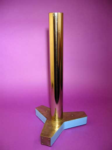
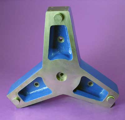
In order to accurately calibrate the large capacity of the Laser Tracker, rather long versions of the “Centerline Ball Bar Rangers” are required. This long distance can generate serious problems due to temperature changes that occur during the calibration cycle that would cause expansion or contraction if ordinary steel were used in its construction. This problem is eliminated by making the tube of the bar from “Invar®”. Invar® is a metal that has almost no thermal coefficient of expansion (it is less than one tenth that of steel) so it is temperature insensitive.
A complete 900 mm stand alone Laser Tracker Calibration System Our Part #CBBR-900- (specify the SMR diameter, .5 or .875 or 1.5 ) includes a 900 mm (35.4 inches ) long “Centerline Ball Bar Ranger,” a Wayout Ball Bar Support, a 14inch (356 mm ) a Heavy Duty Trivet, a 36 inch (941 mm ) tall 3 inch (76 mm ) diameter Anchor, and a Tri-Mount Collar. The price is $2,903.00.
A complete 1500 mm stand alone Laser Tracker Calibration System (Our Part # CBBR-1500, specify the SMR diameter, -.5" or -.875" or -1.5" ),includes a One and a half Meter (1500 mm ) [ 59 inches ] long “Centerline Ball Bar Ranger,” a Wayout Ball Bar Support, a 14 inch Heavy Duty Trivet, a 36 inch (941 mm ) tall, 3 inch (76 mm ) diameter Anchor, and a Tri-Mount Collar. The price is $3,103.00.
A complete 2300 mm stand alone Laser Tracker Calibration System (Our Part # CBBR-2300, specify the SMR diameter, -.5" or -.875" or -1.5" ) includes a two and .3 meter (2500 mm ) [ 98.4 inches ] long “Centerline Ball Bar Ranger”, a Wayout Ball Bar Support, a 14inch (356 mm ) heavy duty Trivet. (our Part# TR-14-HD) a 36 inch (941 mm ) tall, 3 inch (76 mm ) diameter Anchor, and a Tri-Mount Collar. The price is $3,420.00.
For special applications, any custom length Laser Tracker calibration system can be supplied. The Centerline Ranger appears in the Video, "Bal-tec at Quality Expo, 2011" .
Note that the larger size Centerline Rangers may incur a special handling charge by the shipper (UPS Large Package Surcharge ), as they are shipped in long containers.
Laser Tracker Centerline Ball Bar Ranger Pricing
| Part # | Length metric | Length imperial | Nest diameter imperial | Price |
|---|---|---|---|---|
| CBBR-900-5 | 900 mm | 35.4" | 0.5000" | $2,903.00 |
| CBBR-1500-5 | 1500 mm | 59.1" | 0.5000" | $3,103.00 |
| CBBR-2300-5 | 2300 mm | 90.6" | 0.5000' | $3,420.00 |
| CBBR-900-875 | 900 mm | 35.4" | 0.8750" | $2,903.00 |
| CBBR-1500-875 | 1500 mm | 59.1" | 0.8750" | $3,103.00 |
| CBBR-2300-875 | 2300 mm | 90.6" | 0.8750" | $3,420.00 |
| CBBR-900-1.5 | 900 mm | 35.4" | 1.5000" | $2,903.00 |
| CBBR-1500-1.5 | 1500 mm | 59.1" | 1.5000" | $3,103.00 |
| CBBR-2300-1.5 | 2300 mm | 90.6" | 1.5000" | $3,420.00 |
Very Short Ball Bars (Dumbbells) The "Hammer"
Very short Ball Bars (Dumbbells) have become increasingly popular. One of the main applications is filling the need for a traceable calibration of non-contact optical sensing probes and for Coordinate Measuring Machines or Photogrammetry. Our standard mini Ball Bar (Dumbbell) is a viable approach to this problem, but it lacks versatility in that it requires its own mounting system.
This newer approach is the "Hammer". This versatile new device results by rigidly attaching a right angle, three quarter inch ( 3/4", 0.750", 19.05 mm ) diameter handle to the side of any, standard, short Ball Bar (Dumbbell). This new approach provides an economical artifact that is 100% compatible with all of our Ball Bar (Dumbbell) clamping devices. This simple approach allows even the shortest Ball Bar (Dumbbell) to be held on any of our standard Heavy Duty stands or any of the Anchor systems.
The "Hammer" is available in any desired length. It can be provided with master spheres of several different diameters and materials. The most common spherical diameters are one inch (1.00", 25.4 mm), three quarters of an inch (3/4", 0.750", 19.05 mm ) and one half inch (1/2", 0.50", 12.7 mm ). The standard quality of the spheres used on these Ball Bars (Dumbbells) is five millionths of an inch (127 nm) sphericity and common diameter. For ultra precise applications, our grade 2.5 provides a sphericity and common size that is within 2.5 microinches (63 nm).
The most common materials used for the master spheres are a hard Martensitic stainless-steel and ceramic. For calibrating optical devices, satin finished spheres are usually used. Satin finished stainless-steel, titanium and white ceramic are all used for optical probe calibration; but the white ceramic master spheres are the most popular.
The Ball Bar (Dumbbell) Stand
A Rugged Stand for Ball Bar (Dumbbell) Evaluation of Coordinate Measuring Machines. per ANSI / ASME B89.4.1-1997
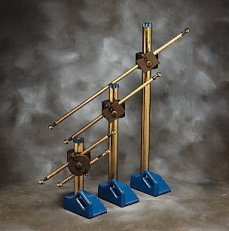
A Ball Bar (Dumbbell) consists of two very round, exactly-matched spheres which are attached to opposite ends of a rather long rigid bar. The exact center to center distance between the two spheres remains constant, while the Ball Bar (Dumbbell) is measured in various positions throughout the X-Y-Z envelope of the Coordinate Measuring Machine. Using this inexpensive tool, an entire C.M.M. system can be quickly and accurately evaluated.
Many companies use C.M.M. evaluation procedures which are based on the Free Standing Ball Bar (Dumbbell). With this technique, the center of the Ball Bar (Dumbbell) is clamped to a vertical post or stand. The advantages of this method include the fact that it is very simple. More data points are collected because the positions of both balls are measured with each move of the Ball Bar (Dumbbell) and that very acute to vertical angles of the bar can be achieved so that a very complete pattern of the machine envelope can be easily explored.
A major error characteristic of the Free Standing Ball Bar is a deflection of the spheres that is caused by the contact force of the measuring probe. Although minor bending of the bar itself is unavoidable, the major source of this deflection has been the bending and twisting of the stand's vertical post. The basis of this problem has been the frail construction of old Ball Bar (Dumbbell) Stands. Most of the present stands in use are adaptations of existing designs previously used to hold indicators. They are not very rugged. By starting with this problem, a totally new vertical stand was developed.
This Ball Bar (Dumbbell) Stand, with its robust 2 inch (50.8mm) diameter hard-clad vertical post, with its heavy interference fit into the 25 lb. (11.34 Kg) cast iron base, eliminates the majority of these deflections. The heavy cast-iron base is fitted with three hardened-steel feet which are precision-lapped flat and coplanar to provide a microinch stable reference surface.
The 14" stand is stable enough to be used without any auxiliary hold down device. For unusual circumstances, a hold down device is available as part number FS-10M-14. A standard hold down device is supplied with all 24” and 36” stands. This hold down device can be used to remove any tendency of these taller stands to tip or rotate. On the bottom of the hold down device there is a 10 millimeter by 1.5” threaded hole. If the threads of your specific CMM table are a different thread size, we have dual threaded adaptor screws available to couple the hold down device to any thread size.
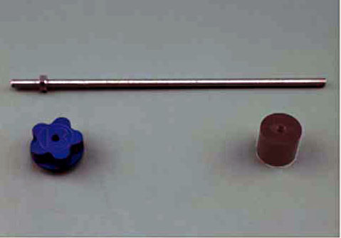
The clamping device that is used to hold the Ball Bar (Dumbbell) on the vertical post is machined from two robust blocks of aluminum. The rear block is machined to form a collar that wraps around the full 360° of the vertical post. A slot in this collar is collapsed by a thread to lock the block securely to the post. The front block is fitted with a long Vee Block which is used to securely hold the Ball Bar (Dumbbell). The front block will allow the Ball Bar (Dumbbell) to rotate a full 360° parallel to the vertical post, allowing a full range of positioning. Both of the blocks are hard anodized for wear resistance
The Free Standing Ball Bar (Dumbbell) Stand is available in three standard heights; Part Number FS-14 is 14 inches (355.6 mm), Part Number FS-24 is 24 inches (609.6 mm) and Part Number FS-36 is 36 inches (914.4 mm). Special heights of vertical stands can be custom manufactured. We will give fast delivery from pre-machined components at very reasonable cost. See ANSI/ASME B89.4.1-1997 for Performance Evaluation of Coordinate Measuring Machines.
The Indicator Arm converts a heavy duty stand into an indicating transfer gage.
Ball Bar Stand and Kit Pricing
| Part # | Description | Price | Purchase |
|---|---|---|---|
| FS-10M | STAND TIE DOWN | $62.57 | |
| FS-14 | BALL BAR STAND 355.6 MM, 14 INCHES, INCLUDES A SINGLE CLAMP, COLLAR | $628.00 | |
| FS-14-0 | BALL BAR STAND ONLY, 355.6 MM, 14 INCHES | $381.00 | |
| FS-14-3-6 | BALL BAR KIT, INCLUDES 300 MM AND 600 MM BALL BARS, STAND, A COLLAR AND DUAL CLAMP | $1367.00 | |
| FS-1BB | SINGLE BALL BAR CLAMP | $151.00 | |
| FS-1BB-S | SMALL BALL BAR CLAMP | $151.00 | |
| FS-24 | BALL BAR STAND 609.6 MM, 24 INCHES, INCLUDES A SINGLE CLAMP, A COLLAR AND A TIE DOWN | $650.00 | |
| FS-24-0 | BALL BAR STAND ONLY, 609.6 MM, 24 INCHES | $401.00 | |
| FS-2BB | DUAL BALL BAR CLAMP | $180.00 | |
| FS-3 | TRI-MOUNT COLLAR, 2 INCH DIAMETER THROUGH HOLE, FOR HEAVY DUTY STAND | $273.00 | |
| FS-36 | BALL BAR STAND 914.4 MM, 36 INCHES, INCLUDES A SINGLE CLAMP, A COLLAR AND A TIE DOWN | $683.00 | |
| FS-36-0 | BALL BAR STAND ONLY, 914.4 MM, 36 INCHES | $488.00 | |
| FS-3BB | TRI-MOUNT COLLAR AND THREE SINGLE BALL BAR CLAMPS | $604.00 | |
| FS-WB | WASHER AND SHOULDER BOLT | $10.80 | |
The Tri-Mount
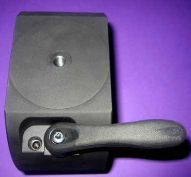
The Tri-Mount™ Ball Bar (Dumbbell) collar is an improvement in the tools for Coordinate Measuring Machine evaluation. The fundamental design of the Tri-Mount allows it to hold three or more separate Ball Bar (Dumbbell)s all at the same time. The Tri-Mount (Part #FS-3) is used with the Heavy Duty Stand (Part #FS-14, FS-24 or FS-36). The Tri-Mount Collar (Part #: AN-3 ) is used with the Anchor (Part #AN-8, AN-12 or AN-24) when small size or light weight are important. This device meets all of the requirements for the "Performance Evaluation of Coordinate Measuring Machines" according to the ANSI B89.4.1-1997 specification.
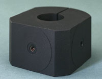
A unique feature of this new device is that it totally eliminates any hand contact with the Ball Bar (Dumbbell) by the calibration technician. This is especially important because all Ball Bar (Dumbbell)s are rather long devices which make them very sensitive to temperature change. There are 20 basic Ball Bar (Dumbbell) positions according to the ANSI B89.4.1-1997 specification. Some of them have the Ball Bar (Dumbbell) horizontal, some have it vertical and some have it at an angle usually approaching 45 degrees. For longer or wider machined, some of these 20 basic positions are repeated and over-lapped so we may end up with 30 or even 35 positions. The Tri-Mount allows all of the positions to be met without once touching the Ball Bar
The same standard Heavy Duty Stand or Anchor and the Tri-Mount hardware can be used over a broad range of C.M.M. The Tri-Mount collar (Part # AN-3) is compatible with any of our existing equipment so you can easily update at very reasonable cost. The location ports on the Tri-Mount will accept the Single Ball Bar (Dumbbell) clamp (Part #FS-1BB) and the Dual Ball Bar (Dumbbell) clamp (Part # FS-2BB) or any length of the Way Out Ball Bar (Dumbbell) supports (see Technical Data Sheet C.M.M.-16, Page 2.) and Cantilever Ball Bar (Dumbbell)s (see Technical Data Sheet C.M.M.-16, Page 1.).
See also, Ball Bar (Dumbbell), Clamp and Collar.
| Part # | Description | Price | Purchase |
|---|---|---|---|
| AN-3 | COLLAR, TRI-MOUNT FOR ANCHOR | $274.00 | |
| FS-3 | TRI-MOUNT COLLAR, 2 INCH DIAMETER THROUGH HOLE, FOR HEAVY DUTY STAND | $273.00 | |
| FS-3BB | TRI-MOUNT COLLAR AND THREE SINGLE BALL BAR CLAMPS | $604.00 | |
A Two Ball Kinematic Coupling for Ball Bar (Dumbbell) Evaluation of CMM
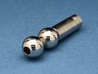
A Ball Bar (Dumbbell) consists of two very round, exactly matched spheres which are securely attached to opposite ends of a rather long rigid bar. The exact distance between the two spheres remain constant while the Ball Bar (Dumbbell) is measured in various positions throughout the X-Y-Z envelope of a Coordinate Measuring Machine. Using this inexpensive tool, an entire CMM system can be quickly and accurately evaluated.
In order to improve the performance of the Ball Bar (Dumbbell), we developed a two ball kinematic coupling. This device provides a rigid support near the very end of the Ball Bar (Dumbbell). The cylinder of the Ball Bar (Dumbbell) rests in a cradle formed by two precision balls. This support eliminates the large bending and twisting errors that normally occur when only the center of the Ball Bar (Dumbbell) is supported. These errors are caused by a multiplication of the contact force of the measuring probe deflecting long unsupported sections of the Ball Bar (Dumbbell).
This Ball Bar (Dumbbell) holding device consists of two very precise, fine grain stainless-steel balls that are hardened to 58 Rockwell C for wear resistance. The two balls are coupled together and rigidly connected to a support. In addition to the obvious cradle formed by the two balls when the coupling is at right angles to the cylindrical bar, the support stand can be rotated more than 30 degrees in either direction, and it will still render the same micro-inch accuracy.
There are three alternative support structures to choose from.
The first alternative supporting structure (Part Number 2B-KM) is a simple cylindrical shaft. The two balls are held on the end of this robust cylinder by a socket head cap screw. This screw passes through concentric holes drilled in the balls. This cylinder in turn is held in the head of one of the Quick Grip Vertical Stands (see Technical Data Sheet CMM-6, Part Numbers QG-14, QG-24 or QG-36).
The second alternative is similar to the first but the two balls are coupled to a powerful magnet by the socket head cap screw. This magnetic base supports the two ball coupling and the coupling supports the Ball Bar (Dumbbell). This inexpensive magnetic coupling, when used with any ordinary shop quality angle plate forms a very rigid deflection-resistant support for the upper end of the Ball Bar (Dumbbell). (Part Number 2B-KM-M).
The third alternative version of this product (part number 2B-KM-H) is made to fit into a height gage or transfer gage stand. Although this type of stand is not as rugged as would be desired, it does form a convenient system that is far superior to supporting the Ball Bar (Dumbbell) by its center. The standard dimensions of the clamping shank is 0.25 inch (6.35mm) wide by 0.5 inch (12.7mm) high. Oversize blanks are kept in stock so that they can be quickly machined to provide custom sized shanks.
The couplings are provided with a safety tether consisting of a loop of plastic-covered steel cable that prevents a crash from sending the Ball Bar (Dumbbell) bouncing across the CMM table. The sphere is supported in the nest of a three ball kinematic platform (see Technical Data Sheet CMM-4, Part Number 3B-KM ) for improved rigidity.
At first glance, it may not be obvious, but these two simple devices have eliminated five of the six degrees of freedom for the Ball Bar (Dumbbell) while giving it very rigid support but without sacrificing one microinch of distortion due to over-constraint from rigid clamping.
For more information on Ball Bar (Dumbbell) evaluation see ANSI/ASME-B89.4.1- 1997 for Performance Evaluation of Coordinate Measuring Machines.
| Part # | Description | Price | Purchase |
|---|---|---|---|
| 2B-KM | TWO BALL KINEMATIC COUPLING FOR QUICK GRIP STANDS | $179.00 | |
| 2B-KM-8 | TWO BALL KINEMATIC COUPLING FOR FS-1BB, BALL BAR | $179.00 | |
| 2B-KM-M | TWO BALL KINEMATIC COUPLING, MAGNETIC | $179.00 | |
| 2B-KM-H | TWO BALL KINEMATIC COUPLING FOR HEIGHT GAGE | $179.00 | |
Ball Bar Bending
A bending moment of the Ball Bar is a second order or cosine error and should be of relatively small consequence. In this case, the bending has a subtle and insidiously serious effect. When the contact force of the measuring probe is applied to the surfaces of the spheres, the resulting bending of the bar will vary dramatically depending on the angular position of the hit. There will be substantial bending perpendicular to the axis of the Ball Bar and absolutely no bending on the very end. When the computer tries to rationalize the input data due to this bending, it sees two much smaller diameter spheres. Because there is no bending at the very ends, the center distance between the two smaller diameter spheres appears to be much further apart.
The Cantilever Ball Bar
The most advanced Ball Bars are of the Cantilever design. They are usually produced to the ultra precise quality and are frequently calibrated as archival artifacts. With this arrangement, there are two additional spheres mounted just behind the master spheres that are used for mounting purposes only. In use, these two auxiliary spheres are held in Kinematic couplings that support the Ball Bar and prevent any bending. In addition to supporting the Ball Bar, this design leaves the complete master sphere available for measurement. This design is entirely compatible with the Way Out Ball Bar Support.
Ultra Precise Ball Bars
A Ball Bar (Dumbbell) consists of two very precise spheres securely attached to opposite ends of a rather long rigid bar. The device is used to evaluate the overall system performance of Coordinate Measuring Machines. The Ultra-Precise Ball Bar (Dumbbell) has spheres which are round and exactly the same size within 2.5 micro-inches (63.5nm). Although sophisticated and very time-consuming laboratory techniques can measure sphericity to a somewhat finer level, 2.5 micro-inches (63.5nm) is generally considered to be the limits of commercial metrology. The surface finish is below 0.5 micro inches (12.7nm). This quality is twice as good as the requirements of ANSI/ASME-B89.4.1-1997 for Performance Evaluating Coordinate Measuring Machines and ten times as good as high quality bearing balls. The absolute size of these Ultra Precise Spheres is held within + or - 0.000020 inch (508nm).
Each Ultra Precision Ball Bar (Dumbbell) is shipped in an individual plastic tube case for permanent protection. Each of our Ball Bar (Dumbbell)s is assigned an individual serial number that is permanently stamped into the bar. A general certification of conformance stating the nominal size and roundness of the spheres is supplied with each Ball Bar (Dumbbell) at no cost.
An individual inspection certification that is traceable to the National Institute for Standards and Technology giving the exact size of each sphere is available. Their sphericity is documented with an individual polar chart recording. The nominal center to center distance between the Ultra Precise Spheres of the Ball Bar (Dumbbell) is documented.
Ultra Precise Ball Bar Pricing, Steel
| Part # | Description | Price | Purchase |
|---|---|---|---|
| UP-BB-200 | BALL BAR, ULTRA PRECISION, STEEL 0200 MM, 7.874 INCHES | $782.00 | |
| UP-BB-300 | BALL BAR, ULTRA PRECISION, STEEL 0300 MM, 11.8 INCHES | $782.00 | |
| UP-BB-350 | BALL BAR, ULTRA PRECISION, STEEL 0350 MM, 13.779 INCHES | $782.00 | |
| UP-BB-400 | BALL BAR, ULTRA PRECISION, STEEL 0400 MM, 15.748 INCHES | $801.00 | |
| UP-BB-450 | BALL BAR, ULTRA PRECISION, STEEL 0450 MM, 17.7 INCHES | $801.00 | |
| UP-BB-500 | BALL BAR, ULTRA PRECISION, STEEL 0500 MM, 19.685 INCHES | $814.00 | |
| UP-BB-550 | BALL BAR, ULTRA PRECISION, STEEL 0550 MM, 21.653 INCHES | $843.00 | |
| UP-BB-600 | BALL BAR, ULTRA PRECISION, STEEL 0600 MM, 23.622 INCHES | $843.00 | |
| UP-BB-650 | BALL BAR, ULTRA PRECISION, STEEL 0650 MM, 25.59 INCHES | $843.00 | |
| UP-BB-700 | BALL BAR, ULTRA PRECISION, STEEL 0700 MM, 27.559 INCHES | $865.00 | |
| UP-BB-750 | BALL BAR, ULTRA PRECISION, STEEL 0750 MM, 29.528 INCHES | $865.00 | |
| UP-BB-800 | BALL BAR, ULTRA PRECISION, STEEL 0800 MM, 31.496 INCHES | $876.00 | |
| UP-BB-850 | BALL BAR, ULTRA PRECISION, STEEL 0850 MM, 33.464 INCHES | $878.00 | |
| UP-BB-900 | BALL BAR, ULTRA PRECISION, STEEL 0900 MM, 35.433 INCHES | $878.00 | |
| UP-BB-950 | BALL BAR, ULTRA PRECISION, STEEL 0950 MM, 37.401 INCHES | $879.00 | |
| UP-BB-1000 | BALL BAR, ULTRA PRECISION, STEEL 1000 MM, 39.37 INCHES | $879.00 | |
Ultra Precise Ball Bar Pricing, Invar®
| Part # | Description | Price | Purchase |
|---|---|---|---|
| UP-BB-INV-200 | BALL BAR, ULTRA PRECISION, INVAR® 0200 MM, 7.874 INCHES | $892.00 | |
| UP-BB-INV-300 | BALL BAR, ULTRA PRECISION, INVAR® 0300 MM, 11.8 INCHES | $892.00 | |
| UP-BB-INV-350 | BALL BAR, ULTRA PRECISION, INVAR® 0350 MM, 13.779 INCHES | $892.00 | |
| UP-BB-INV-400 | BALL BAR, ULTRA PRECISION, INVAR® 0400 MM, 15.748 INCHES | $911.00 | |
| UP-BB-INV-450 | BALL BAR, ULTRA PRECISION, INVAR® 0450 MM, 17.7 INCHES | $911.00 | |
| UP-BB-INV-500 | BALL BAR, ULTRA PRECISION, INVAR® 0500 MM, 19.685 INCHES | $924.00 | |
| UP-BB-INV-550 | BALL BAR, ULTRA PRECISION, INVAR® 0550 MM, 21.653 INCHES | $953.00 | |
| UP-BB-INV-600 | BALL BAR, ULTRA PRECISION, INVAR® 0600 MM, 23.622 INCHES | $953.00 | |
| UP-BB-INV-650 | BALL BAR, ULTRA PRECISION, INVAR® 0650 MM, 25.59 INCHES | $953.00 | |
| UP-BB-INV-700 | BALL BAR, ULTRA PRECISION, INVAR® 0700 MM, 27.559 INCHES | $975.00 | |
| UP-BB-INV-750 | BALL BAR, ULTRA PRECISION, INVAR® 0750 MM, 29.528 INCHES | $975.00 | |
| UP-BB-INV-800 | BALL BAR, ULTRA PRECISION, INVAR® 0800 MM, 31.496 INCHES | $986.00 | |
| UP-BB-INV-850 | BALL BAR, ULTRA PRECISION, INVAR® 0850 MM, 33.464 INCHES | $988.00 | |
| UP-BB-INV-900 | BALL BAR, ULTRA PRECISION, INVAR® 0900 MM, 35.433 INCHES | $988.00 | |
| UP-BB-INV-950 | BALL BAR, ULTRA PRECISION, INVAR® 0950 MM, 37.401 INCHES | $989.00 | |
| UP-BB-INV-1000 | BALL BAR, ULTRA PRECISION, INVAR® 1000 MM, 39.37 INCHES | $989.00 | |
The Gage Block Clamp
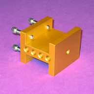

The Ball Bar is such an outstanding device for C.M.M. evaluation that we often ignore the ANSI B89.4.1 requirement that a gage block must also be measured for a complete calibration (evaluation). Now you can use your own gage blocks. The problem of how to hold the gage block and how to present the gage block in various locations is solved by using our “Gage Block Clamp,” our Part# GC-2 The old technique of using two separate stands, one to hold the gage blocks and one to hold the Ball Bar, was cumbersome and expensive. The Gage Block Clamp solves this problem in a very compact and inexpensive way.
The design of the Gage Bock Clamp consists of a rigid block of metal that is machined to hold two gage blocks simultaneously. The two gage blocks used are usually three inches (3.0”, 76.2 mm) and four inches long (4.0”, 101.2 mm). Each gage block is held in position by two thumb screws. This Gage Block clamp is universal in that it will hold either standard rectangle or Square Gage Block. To add even more versatility and economy to this device, a pair of adjustable ball bar balls (our Part # ABB-PB-100) may be attached, one to the end of the Gage Block Clamp, and one to the end of the Adjustable Ball Bar on the opposite end. This will turn the Ball Bar Clamp into a fully functioning Ball Bar.
Our standard 200 mm length of our Adjustable Ball Bar system is used as the handle. This bar is held in our Single Ball Bar Clamp on one face of the Tri-mount Collar mounted on the Freestanding Ball Bar Stand.
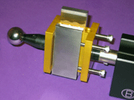
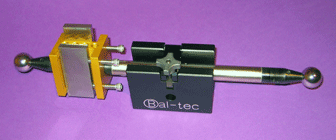
Gage Block Clamp Component Pricing
| Part # | Description | Price | Purchase |
|---|---|---|---|
| GC-2 | Gage Block Clamp incl. handle and ball bar clamp | $163.00 | |
Long Gage Block Clamp Gage Block Clamp for Long Blocks Holder for Long Gage Blocks
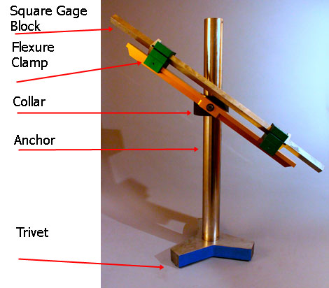
There is a wave of interest going through the C.M.M. calibration community to augment Ball Bar measurements with the measurement of calibrated, "long" gage blocks. Many companies already have sets of long, square gage blocks and only need a method of supporting them for measurement. The Long Gage Block Clamp answers this need in very unique ways.
The problem of holding long gage blocks is simplified by the “Aeries” concept. Where the support mechanism for Ball Bars must be as long as the Ball Bar itself, the support mechanism for long gage blocks only needs to be 57% as long as the gage block. At 57% support, the ends of the gage blocks end up the most parallel. This length is defined as the Aries points.
Our Long Gage Block Clamps use a very unique, semi-kinematic, clamping mechanism that holds the gage block very securely but without bending moments. The Long Gage Block clamp is designed to be used with any of our standard Ball Bar holding systems, such as the Heavy Duty Stands or the Trivet and Anchor combination.
The semi kinematic clamping system is available in two versions. The simplest version is our part number LGBC uses two sets of Vee-Blocks that adjustable up and down the rail. They are cylindracized, so they only contact the gage block along four self adjusting lines. The support rail and gage block clamps are made of aircraft quality aluminum, which has a thermal coefficient of expansion that is twice that of steel, and twelve times invar.
If temperature changes occur during a calibration, it is possible that this difference in thermal properties could cause problems. To limit this possibility, we produce a version of the Long Gage Block Clamp, our part number LGBC-F which has one of the clamping device mounted on flexures, to provide automatic thermal adjustability.
We offer the Way Out support rail for the Long Gage Block Clamp in three standard lengths:
- The sixteen inch (16”) [406.4 mm ] long, way out support rail, part number WO-762-16.
- The twenty inch (20”) [508 mm ] long, way out support rail, part number WO-762-20.
- The thirty inch (30”) [762 mm ] long, way out support rail, part number WO-762-30.
To prevent any possibility of the gage block sliding out of the gage block clamps, we provide two of our gage block locking rings with each set of long gage block clamps. The Long Gage Block clamp is designed to be used with any of our standard Ball Bar holding systems such as the Heavy Duty Stands or the Trivet and Anchor combinations. When ordering, specify the part number of rail required and which of the clamping systems you prefer.
Collar for long gage block clamp — Extra long collar for 3 inch posts — Very long collar for 3 inch posts
This extended collar is for holding large artifacts, such as the very long gage blocks, in conjunction with a long gage block clamp on any of our three-inch (76.2 mm) diameter posts. It is compatible with any of our three-inch diameter hardware. This device is part number ELC-3. It is four inches (101.6 mm) square and 8.250 inches (209.55 mm) from end to end. This spaces the artifact being held 2.62 inches (66.548 mm) away from the 3-inch diameter column.
There is a threaded 3/8"-16 hole in each of the four by four inch ends. There is also another 3/8"-16 thread hole in the flat front face on either end. This very rigid device is used to hold large artifacts further away from the three-inch diameter column than the standard trimount collar. This is so that a long artifact can be rotated 360-degrees vertically without running into the supporting structure. We use a unique close-up clamping system on this device that incorporates a left and right threaded turnbuckle-like clamp, that grabs the three inch column like an alligator. For its large size, this extended collar is light-weight at only 11.5 pounds (5.216312 kilograms).
Long Gage Block Clamp Specifications
| Part Number with the Simple Clamp | Length of Rail |
|---|---|
| LGBC-WO-406-16 | 16 inches (406.4mm) |
| LGBC-WO-508-20 | 20 inches (508mm) |
| LGBC-WO-762-30 | 30 inches (762mm) |
| Part Number with the Flexural Clamp | Length of the Rail |
|---|---|
| LGBC-F-WO-406-16 | 16 inches (406.4mm) |
| LGBC-F-WO-508-20 | 20 inches (508mm) |
| LGBC-F-WO-762-30 | 30 inches (762mm) |
The Geostep™ 3400-10 (*discontinued, we have a limited parts still in stock).
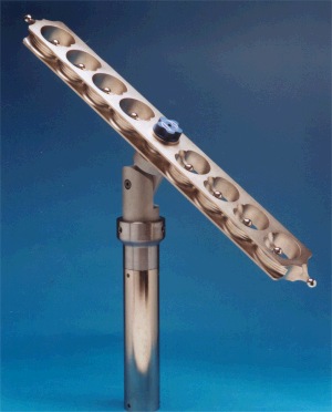
The Geostep™, model 3400-10 has ten ultra precise spheres permanently mounted on the centerline of a very rigid beam. This one universal tool is the only device required to fully calibrate most Coordinate Measuring Machines. After the Geostep™ 10 is properly calibrated, it becomes a fully traceable secondary standard. In addition to its ability to perform a full-scale machine calibration, the Geostep™10 will do an interim or Monday morning evaluation of the machine in just a matter of minutes.
When trouble shooting to locate problems that occur with the machine's performance, the data collected from the simple in line design of the Geostep™10 are very easy for the calibration technician to interpret.
The unique three-dimensional characteristic of the spherical artifacts used on the Geostep™10 make them the ideal geometry for C.M.M. evaluation. There are no flatness or parallelism errors. There are no alignment or cosine errors of either the artifact or its positioning on the machine. This is because the origin of the spherical surface is perfectly defined by its radius as a single infinitely small address in three-dimensional space.
The GeoStep Blue Print
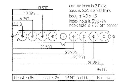
The Geostep™10 is a Ball Plate. It is a Ball Bar (Dumbbell). It is a step standard. It weighs only 20 pounds (9.0 kg), but the unique design makes it extremely rigid. All of the spherical artifacts are arranged on the center line or neutral bending plane of the beam. Any minute bending that does occur due to gravitational attraction or probing force will cause only very small second order cosine errors in the true position of the spherical artifacts.
The beam or frame of the device is produced by the special Stable Cast™ process. This near net shape process creates a metallurgically sound structure with very little retained austenite, so that its long term dimensional stability is assured. The rugged beam of the Geostep™10 is 1.5 inches (38.1mm) thick and 4.0 inches (101.6mm) wide. The overall sphere center to sphere center dimension is approximately 850mm or (33.46 inches). The substantial reach of the Geostep™10 is more than twice that of a standard 400mm (15.75 inches) Ball Plate. A single technician can do the entire set up and calibration of the machine, because the Geostep™10 has a weight of less than 20 pounds (9 kg).
Each of the ten sphere center to sphere center dimensions are approximately 85mm or (3.34 inches) apart. These ten spheres provide 45 sphere center to sphere center dimensions. These center to center dimensions are intentionally varied from sphere to sphere. This feature is used to prevent any possible systematic errors in the scale system from falling into a matching pattern with the step standard. The ten 0.748 inch (19mm) diameter reference spheres are exactly the same diameter and spherical within less than 5 microinches (.13 micro meter). The standard spheres are produced from extremely fine grain, stainless-steel that is hardened to 58 HRC and is thermally treated for long term dimensional stability. We also offer fine grain, high-density ceramic spheres.
The important feature of the particular ceramic used is that it has the same stiffness as steel, so that the calibration is not distorted due to differential elastic deformation. The extremely large 3.00 inch diameter window around the master spheres gives more than enough pretravel of the measuring probe to produce very reliable measurements on any make of Coordinate.Measuring Machine. A standard ball plate with 25 balls, has 300 potential sphere center to sphere center addresses. The Geostep T10 has 45. The number of addresses is very important because you need enough to do a good machine evaluation, but the yearly calibration of too many addresses becomes a very expensive proposition indeed.
The GeostepT10 can be used to characterize (calibrate) the test probe. It can be used to perform the repeatability test, and it is extremely well suited to evaluate the temperature drift effect.

The rugged universal holding device used to locate the GeostepT10 on the C.M.M. table can rigidly position it for vertical horizontal or angular probing. This holding device is based on our well-proven Anchor line of Ball Bar (Dumbbell) support devices. It consists of a rugged 3.0-inch (76mm) diameter steel post with a kinematically coupled tie down bulkhead. The upper structure provides full three degrees of freedom positioning of the GeostepT10. It can be rotated the full 360 degrees horizontally. It can articulate the full 180 degrees vertically and the Geostepª10 can rotate the full 360 degrees on its own axis.
A special kinematically coupled base plate, Part Number 3400-10, is available as an accessory to achieve the very low horizontal positions.
Low Horizontal
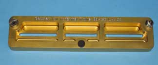
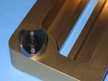
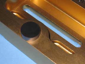
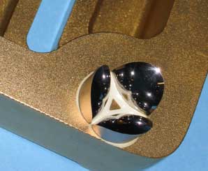
Optionally, the Geostep 10 can have one rail lapped straight within less than one micrometer (40 microinches). This is a popular device for evaluating "Z" axis roll. To add this feature, order the GeostepT3400-10. The GeostepT10 will evaluate every one of the twenty one (21 ) theoretical C.M.M. rigid body errors. These include the accuracies of the X, Y and Z scales, the straightness of the X, Y and Z movements, the squareness of the X, Y and Z movements, each one of the three rotational errors that can occur in each one of the three axii.
In addition to measuring these 21 straight forward geometry and scale errors, the GeostepT10 will quantify the effect of the flexing or bending of the machine's mechanical structure, so that realistic measurement uncertainty can be assigned to the machine. The Geostep is used with a 14" Trivet.
Geostep, Model 2600-8 (*discontinued, we have a limited parts still in stock).
The Geostep 8 is simply a shorter version of the basic GeostepT, model 3400-10, it has eight spheres. The beam of the device is the standard one and one half inch (38.1mm) thick by 4 inch (101.6mm) wide. It has an overall sphere center to sphere center of 26.625 inches (676.3mm). This smaller device is equipped with a stand of appropriate height. There is a special accessory base plate, Part # BP-2600-8, used to achieve the low horizontals.
Geostep, Model 1600-6 (*discontinued, we have a limited parts still in stock).
The Geostep 6 is a shorter version of the model 3400-10, it has six spheres. The overall sphere center to sphere center is 16.687 inches (424mm). This shortest version of the GeostepT is equipped with a stand of appropriate height. The accessory plate for achieving the low horizontals for the Model 6 is Part # BP-1600-6.
Geostep Pricing (*discontinued, we have a limited parts still in stock).
| Part # | Description | Price | Purchase |
|---|---|---|---|
| GEOSTEP 3400-10 | GEOSTEP 3400-10 | $5280.00 | |
| GEO-LHKS | GEOSTEP, LOW HORIZONTAL KINEMATIC SUPPORT | $385.00 | |
| GEO-LSE | GEOSTEP, LAPPED STRAIGHT EDGE OPTION | $385.00 | |
| 1600-6 | GEOSTEP, SIX SPHERES | $5280.00 | |
| 2600-8 | GEOSTEP, EIGHT SPHERES | $5280.00 | |
The Trivet — A Different Tripod — Trivets 7", 14", and 18"
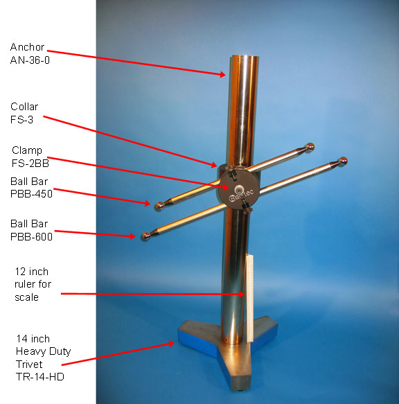
As the name implies, this is a three-legged mechanical base. The outstanding features of the "14-inch Trivet" are its lightweight, its extreme rigidity and its excellent mechanical stability. The "Trivet" has a large fourteen inch 14" (356 mm) diameter footprint, that provides the required mechanical stability.This design is built around a very lightweight, but still extremely rigid, aircraft quality aluminum casting.
The "Trivet's" primary functions are to provide a lightweight, mechanically stable stand, to hold calibration artifacts during Coordinate Measuring Machine evaluation or to support scientific apparatus. The lightweight of the "Trivet" is of special importance, when the equipment must be transported all over the country by the calibration technicians. The standard version of the "Trivet" has three large seven eights of an inch 0.875" (22 mm) diameter hard stainless-steel buttons, that are permanently attached to the three feet on the outer periphery of the "Trivet". These buttons are precision lapped flat and coplanar to provide the ultimate in dimensional stability.
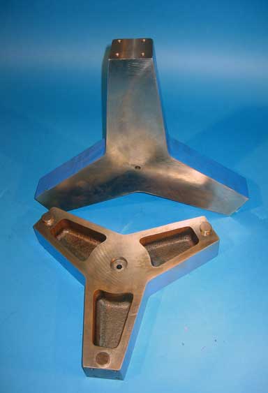
The wide equilateral span between the three feet of the "Trivet" is necessary to make up for its very lightweight.
There are a series of M10 X 1.5 threaded holes provided at strategic locations in the top surface of the flat platform. These threaded holes are used to rigidly attach any of the different length Anchors that may be required for stable location.
A complete 1000 mm stand alone Laser Tracker Calibration System includes a One Meter (1000 mm ) [ 39 inches ] long “Centerline Ball Bar Ranger,” (our Part #CBBR-1000, specify the SMR diameter), a Wayout Ball Bar Support, (our Part #W0-10) a 14inch Heavy Duty Trivet, (our Part #TR-14-HD) a 36 inch (941 mm) tall, 3-inch (76 mm) diameter Anchor (Our Part #AN-36-0) and a Tri-Mount Collar (Our Part# AN-3). This complete set of parts is #CBBR-1000-INV-KIT.
The top surface, of the standard version, of the "Trivet", is two inches three hundred thousandths of an inch 2.300" (58.5 mm) above the base plane. This top surface is ground flat and parallel to the three large flat feet. In addition to the standard off the shelf hardware, custom designed clamping systems can be adapted to hold special equipment, rigidly on top of the Trivet.
Scientific Equipment Mounting
The standard "14 inch Trivet" with the appropriate length "Anchor" and mounting hardware can provide a most stable vertical mounting system for Microscopes, Telescopes and other Scientific apparatus.
Kinematic Mounting
As an alternative to the three flat buttons the three feet of the "Trivet" can be equipped with Kinematic vee blocks, Part number TR-14-AL-SVB, that mate with the spheres of our Three Bar Kinematic system (see under pre-assembled Kinematic Platforms) for mounting on optical tables or other bread board apparatus. Using this arrangement the "Trivet" with its payload can be located, removed, and replaced within arc-seconds. Using this arrangement it can also be indexed in very accurate increments of 120 degrees.
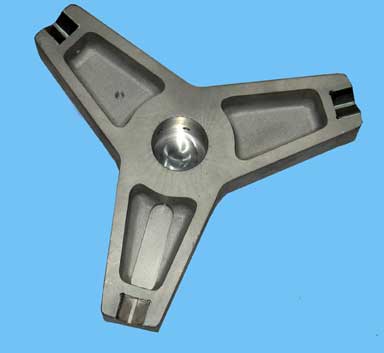
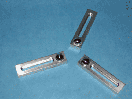
Raw Casting
The raw casting for the Trivet is available for special projects that customers may choose to do in house, at a cost of $117.00 each. This casting is also available with the top surface Blanchard ground for $127.00 each.
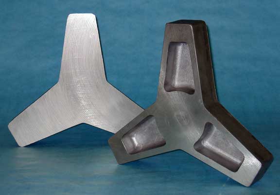
Pricing
| Part # | Description | Price | Purchase |
|---|---|---|---|
| TR-7-AL | TRIVET, 07 INCH, ALUMINUM | $264.00 | |
| TR-14-AL | TRIVET, 14 INCH, ALUMINUM | $492.00 | |
| TR-14-HD | TRIVET, 14 INCH, IRON | $440.00 | |
| TR-18-AL | TRIVET, 18 INCH, ALUMINUM | $633.00 | |
| TR-18-HD | TRIVET, 18 INCH, IRON | $581.00 | |
Giant Laser Tracker Evaluation Device
The Laser Tracker has become an alternative for evaluating very large Coordinate Measuring Machines. This Giant Invar® Ball Bar (Dumbbell) provides the means for making an ANSI- B89.4.1-1997 evaluation of Laser Trackers. The Giant Invar® device used for this application has a magnetically preloaded, Three Ball Kinematic Coupling mounted on each of the end bulkheads.
To make the evaluation, a spherical corner cube or cats eye is placed in the first Three Ball Kinematic Coupling and a reading is taken. The corner cube or cats eye is then moved to the second Three Ball Kinematic Coupling and another reading is taken. This pattern is repeated in each of the 20 to 35 ANSI positions. As the dimension from center to center of the two Three Ball Kinematic Couplings is absolutely fixed, any deviations in length measured are errors in the performance of the Laser Tracker System.
Modular Design
The modular design of the Giant Ball Bar (Dumbbell) allows for construction of any length structure by simply using that length of Invar® tubing. This unique feature adds a great deal of versatility and economy to the Giant Ball Bar (Dumbbell). The same component parts can be assembled with different lengths of Invar® tubing to form, a family of different length Giant Ball Bar (Dumbbell)s.
The support mechanism used for the Giant Ball Bar (Dumbbell) must have the same basic qualities as the Ball Bar (Dumbbell) itself. To do this, we have devised tripod assemblies based on the same basic structure as the Giant Ball Bar (Dumbbell) itself. Because of this light weight tubular Invar® construction the tripods can be easily dismantled for transportation and storage. At the same time they are very rigid and manifest the extreme temperature stability characteristic of low expansion rate of the Invar®.
Pricing
| Part # | Description | Price | Purchase |
|---|---|---|---|
| GBB | GIANT BALL BAR | $2101.00 | |
| TRI | TRIPOD FOR GIANT BALL BAR | $2090.00 | |
| GBB-TRI | GIANT BALL BAR WITH TRIPOD | $4191.00 | |
Portable Arm Coordinate Measuring Machines Calibration
For reliable evaluation of the Portable Arm Coordinate Measuring Machines, rather large calibration artifacts are required. Although a number of different length artifacts have been supplied the industry is trying to standardize on 2.3 meters (90.55"). These large calibration devices must remain dimensionally stable during the evaluation sequence. This dimensional stability must be physical stability. By this we mean that the - must not distort mechanically when the test probe actually makes physical contact with the calibration object.
This mechanical stiffness must be maintained on these rather large devices but at the same time they must still be light weight enough for portability in the field and so that a single technician can manipulate them through the 20 to 35 positions required to meet the ANSI B89.4. 1-1997 specification for the "Performance Evaluation of Coordinate Measuring Machines". This rather daunting problem is further complicated by the fact that large objects are very sensitive to small variations in temperature. An eight foot (96-inch) [two point four meter] long aluminum bar will expand more than one thousandths of an inch (.025mm) for each degree F. of temperature rise. For steel it is over one half of a thousandths of an inch (.013mm) per degree F.
The same eight-foot (two-point four-meter) structure made of Invar® will only expand sixty-five microinches (1.7 micro meters) per degree F. The realization of lightweight, good rigidity and low temperature sensitivity are all achieved by building a composite structure of a series of round tubular Invar® members, clamped together by a number of robust bulkheads. The tubular structure provides the stiffness and the lightweight while the ultra low expansion properties of Invar® solves the temperature sensitivity problem.
This large device must be supported on a metrology platform with the same rigidity, light weight and low temperature sensitivity as the artifact itself, so we have devised a Metrology Tripod with the very same design features as the Portable Arm C.M.M. Calibrator. The large tubular Invar® structure is supported on the tripod by a ball bearing turret that allows it to be easily positioned at any angle from vertical to horizontal.
There is another unique problem in evaluating the performance of a portable arm C.M.M. When using a hard probe it is difficult to make a single only contact with a small calibration artifact. This is even more difficult, when probing a sphere, which is the standard A.N.S.I. artifact. The machine has difficulty identifying one only point on an infinitely varying target. A unique way to cope with this problem while still using a spherical target has been developed. A very precision sphere of rather large diameter between 0.59 -1.00 inch (15 mm to 25 mm ) is used as the measuring probe. A Three Ball Kinematic Coupling is rigidity mounted on the face of each of the four bulkheads that hold the Invar® tubing together and a fifth is mounted on the top center of the turret. By placing the large probe sphere in the Three Ball Kinematic Coupling, a single only point in three-dimensional space is described. In order to make the hit more positive the Three Ball Kinematic Coupling has a light magnetic preloading.
The Kinematic Coupling is made up of three high grade, five sixteenths of an inch (5/16", 0.3125", 7.9 mm ) diameter tungsten carbide balls. Each of these balls have a deep hole drilled in them. At assembly they are glued, over a high shear strength pin, into individual spherical cavities in the face of the bulkheads. This design provides maximum strength with great shear resistance and a very thin glue line that prevents hygroscopy due to moisture absorption.
Simplified C.M.M Evaluation
In the modern Coordinate Measuring Machine environment, a quick and dirty once a year calibration of your C.M.M. just won’t cut it any more. You need to do a frequent, multi-step, in depth evaluation of your machine’s geometric envelope. This is much simpler and far less expensive than you can imagine. The secret weapon in this battle is the ultra accurate but very inexpensive Ball Bar (Dumbbell) System. Are the elements of your C.M.M.’s metrology frame straight and square enough to accurately guide the measuring probe on its assigned task?
As modern measuring probes have become more complex, they are presenting even greater probabilities that serious machine errors will manifest themselves as erroneous measurements.
Compound, Star and Tree test probes place stringent new disciplines on “Z” axis, rotation or roll. When using complex probes on older machines, a serious evaluation of the “Z” axis roll is even more critical as these machine designs have only crude provisions to control this rotational problem. Articulating measuring probe heads add position-indexing accuracy to the already complex quality equation. When you add automatic measuring probe changers to the equation, the potential error budget of the overall system can be doubled again. Many very substantial error sources such as, loose probe tips, perturbations in air pressure, and temperature variations have simple solutions once the error sources have been identified using the simple, inexpensive Ball Bar (Dumbbell) system.
One company found large disparities between the hole pattern they had programmed and the resulting hole pattern that was measured by a brand new Coordinate Measuring Machine. When they checked this brand new Coordinate Measuring Machine with a Ball Bar, (Dumbbell) they found that this certified in place machine had a serious “X” to “Z” axis squareness problem. This error had somehow been overlooked by the calibration technician when the machine was originally set up and “certified”.
A Ball Bar (Dumbbell) system consists of a Ball Bar, (Dumbbell), a very rugged supporting stand and some arrangement to rigidly attach the Ball Bar (dumbbell) to the stand (Clamp). A Ball Bar or Dumbbell is made up of two very spherical balls of exactly the same diameter securely attached to a rather long rigid bar. By measuring the Ball Bar (Dumbbell) in a number of different positions, a full evaluation of the Coordinate Measuring Machine’s 18 geometry related rigid body error sources can be made. All of the potential elastic or bending errors are variations of the 21 parametric error sources that can be evaluated in the same way. By using multiple Ball Bars (dumbbells) that have an accurately calibrated length, the three potential scale errors can be added to this equation, thus completing a full evaluation of the 21 potential parametric machine errors.
Stand Tie Down
Part No.: FS-10M
Pricing
| Part # | Description | Price | Purchase |
|---|---|---|---|
| FS-10M | STAND TIE DOWN | $62.57 | |
Three Ball Kinematic Mount — Time-Saving Ball Bar (Dumbbell) Fixture
Part Number 3B-KM
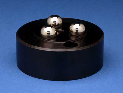
The Three Ball Kinematic Platform (our Part Number 3B-KM) can be used with any Ball Bar (Dumbbell) having approximately one inch (25.4 mm ) diameter spheres. This tool will allow you to evaluate a Coordinate Measuring Machine in one half the time required by conventional means. It does this by reducing the number of measurements that must be taken.
A micro-inch accurate reference datum is created at one end of the Ball Bar (Dumbbell). This fixed reference datum consists of a three ball kinematic coupling mounted on a rugged steel platform. One of the spherical ends of the Ball Bar (Dumbbell) rests in the nest formed between the three high quality stainless-steel balls. The opposite end of the Ball Bar (Dumbbell) can now be swept to describe a micro inch accurate hemispherical shell. While many X-Y-Z positions of this outer sphere are measured, only one measurement for the original position of the reference datum ball is required.
The Three Ball Kinematic Coupling is of unique design. It consists of three ultra fine-grain truncated stainless-steel balls that are hardened to 58 Rockwell C for long wear. The precision flat ground bases of the three balls are held solidly against the rigid steel platform from below by three socket head cap screws. These high quality balls are .750 inch (19.05mm) diameter with a blind bottom 1/4 inch (6.35mm) diameter hole, with 20 threads per inch (metric threads will be supplied on request). This design allows the kinematic balls to be indexed to literally hundreds of new positions, thus assuring many years of quality use.
NOTE:
We also stock several standard diameters of truncated and threaded kinematic balls which are available separately for your special tooling applications. See our Kinematic Components Catalog #105 (Truncated and Threaded Balls).
Pricing
| Part # | Description | Price | Purchase |
|---|---|---|---|
| 3B-KM | THREE BALL KINEMATIC PLATFORM, 4" | $215.00 | |
The Universal Four-Inch Platform
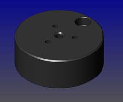
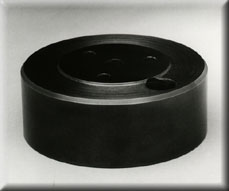
| Downloads | ||
|---|---|---|
| Solidworks | IGES | |
The 4 inch platform (part number PLT-4 ) is a universal mounting tool. It is used to securely couple a variety of measuring devices to the machine under test. Among these devices are all of the CMM probe characterizing spheres on a post including the Mini Ball Bar (Dumbbell). The 45 degree Angle block (Part Number BLK 45) is designed for use with the four inch (101.6 mm ) platform . For performance evaluation of Computer Numerically Controlled machining centers, it will hold the standard 1.00 inch (25.4 mm ), part number PM-UB-B100, diameter Ultra Precise Test Sphere on the 1-1/4 inch (31.75 mm ) diameter post. It will also hold "The Big One", a two inch (50.8 mm ) diameter Test Sphere mounted on a 2 inch (50.8 mm) diameter by 2-1/2 inch (63.5 mm ) high post.
All of these tools are coupled to the platform through a M10 x 1.5 diameter threaded stud. The platform has a tapped hole directly in the center and one near the outer edge of the top face. All of the accessories have corresponding tapped holes in them. In addition to the central tapped hole, there are three 1/4 inch (6.35 mm ) diameter holes drilled through the platform and counterbored from the bottom. These three holes form the vertices of an equilateral triangle. They are used to mount three 3/4 inch (19.05 mm ) diameter truncated and tapped spheres to form the three Ball Kinematic Platform (Part Number 3B-KM, Technical Data Sheet CMM-4) used in Ball Bar (Dumbbell) evaluation of Coordinate Measuring Machines.
This platform is manufactured from a free machining low alloy carbon steel. It may be easily modified to provide extra holes, threads, or other details. Prompt delivery of any modified configuration will be supplied at reasonable cost. This robust steel platform is four inches (101.6 mm ) diameter and 1-1/2 inch (38.1 mm ) thick. It weighs over five pounds ( 2.27 kg ). There is a recess machined in its base that leaves an annular ring around the edge. This ring is precision lapped flat to form an excellent coupling to a CMM or machine tool table.
There is a drilled and counterbored hole through the platform that will accept a 3/8 inch or a 10mm diameter socket head cap screw. This screw will securely clamp the platform to its mating surface. The 4" platform is supplied with an attractive black oxide finish which helps to retard corrosion. Other finishes are available on special order. The platform is often used with the Dual Threaded Adaptor Screws.
Pricing
| Part # | Description | Price | Purchase |
|---|---|---|---|
| PLT-4 | PLATFORM, 4 INCHES | $158.00 | |
Vision System Calibration with Ball Bars (Dumbbells, VDI/VDE )
Technical Information
There are two schools of thought on balls for vision systems. The first is aluminum oxide ceramic, which works well and isn't expensive in small diameters, 1.00 inch (25.4 mm ). The price goes out of sight for anything over 2.00 inches (50 mm ) diameter. Satin finished titanium is being widely used in some circles, and doesn't get too expensive until you get over 4.00 inches ( 100 mm ) diameter. The dumbbells are manufactured to nominal lengths. When balls of different sizes are put on each end of the dumbbell, serious metrology problems are generated. Determining the axis and compensating for elastic deformation is nearly impossible.
Our calibration uncertainty is limited to + or - three microns. N.I.S.T., P.T.B. or N.P.L. can give sub parts per million calibration. Our standard one inch diameter satin finished ceramic balls on an Invar® bar costs $426.00. N.I.S.T. traceable calibration is $146.00. Normal delivery is four weeks.
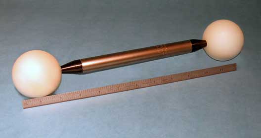
Our standard two inch diameter satin finished ceramic balls on an Invar® bar are $1,446.00. N.I.S.T. traceable calibration is $146.00. The bars are black satin finished. We offer the standard, satin finished, titanium straight edge that is one and one half inches (38.1 mm ) wide by eight inches (203.2 mm ) long at $486.00. The flatness tolerance is one micrometer. Estimated delivery is three weeks. We can quote any length and width up to 34 inches (863.6 mm ) long on a custom basis.