Bal-tec™ Home All Kinematic Platforms
All Kinematic Platforms
The 3" × 3" Pre-assembled Kinematic Platform
| Downloads | |||
|---|---|---|---|
| Part # | Solidworks | IGES | |
| KP-3-3 | |||
| KP-3-3-P | |||
| KP-3-3-T | |||
| KP-3-3-CS | |||
| SP-3-3 | |||
| KP-3-BAR | |||
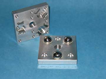
The 3-inch by 3-inch (76 mm x 76 mm) Kinematic Platform is now available as a plug-and-play device. This extremely small platform will carry an enormous 50-pound load. This is a petite design, but it is not a toy. Its robust construction uses one-half inch (0.50", 1/2", 12.7 mm) thick aluminum. When assembled, the overall height of this kinematic platform, from bottom to top, is one and one-eighth inches (1 1/8", 1.125", 28.6 mm).
Top Kinematic Platform
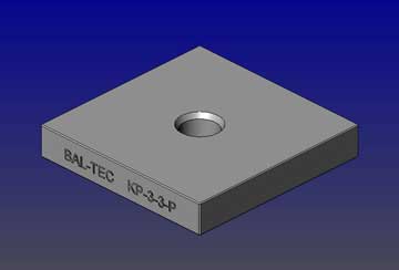
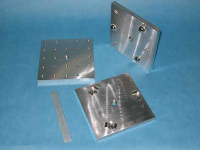
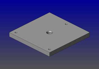
There are two standard versions of the top kinematic platform. One version has a plain, flat upper-surface that our customers can custom-tailor to hold the apparatus they want to mount on it, or we will bid machining the details to your blue print or rough sketch, Part number KP-3-3-P. The second version of the top platform has eight 1/4" inch (6.3 mm) by 20 threads per-inch drilled and tapped holes around the edge and two additional holes on the centerline in the ", (1.25", 31.75 mm) inch apart. The top surface is ground flat. This version of the top is Part number KP-3-3-T.
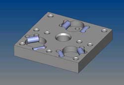
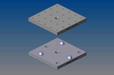
The Kinematic seats in the top platform use three pairs of precision cylinders that form three vees. These cylinders are ground and precision-lapped to a surface texture that is less than 1.0 microinch (25 nanometers) Ra. These six cylinders are glued into three precision-machined trenches with a ceramic filled epoxy to provide absolute rigidly. The six cylinders are made of the same material and processed in exactly the same way.
This contrasts with commercial dowel pins that are used in competitive products. These ground-only carbon steel dowel pins are prone to rust and are very susceptible to fretting, which is one of the major problems of kinematic couplings.
Bottom Kinematic Platform
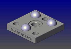
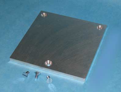
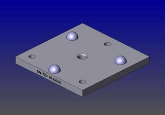
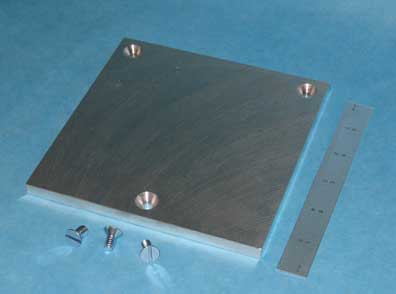
There are also two standard versions of the bottom platform. The first is a three-inch by three-inch (3" X 3", 76 mm X 76 mm) by one half-inch (0.5", 1/2", 12.7 mm) thick aluminum plate. Model number KP-3-3-CS, it is made for custom mounting to the mating structure and has three one-quarter inch (0.25", 1/4", 6.3 mm) diameter counterbored holes that will accept standard one-quarter inch (0.25", 1/4") or 6 mm diameter socket head cap screws.
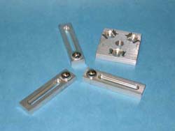
This version is the truly a universal design. It will adapt to any optical table or tee slotted arrangement.Simple drilled and tapped holes will securely fix it to its mating structure. The second standard version of the bottom platform, KP-3-BAR, consists of three individual bars of the following dimensions: one inch wide (1", 25.4 mm), one half-inch thick (0.5", 1/2", 12.7 mm), and four-inch long (4", 101 mm).
Each bar has a super-accurate three-quarter inch (0.75", 3/4", 19 mm) diameter sphere, rigidly mounted on one end. There is a three inch ( 3", 77 mm) long, recessed-slot that will accept a one-quarter inch or six millimeter (0.25", 1/4", 6 mm) socket head cap screw opposite this. Also available is Part number KP-MG-BAR is also available to hold a powerful magnet for preloading the Kinematic Platform. In staying with an industrial design, this platform uses three large, three-quarters of an inch (0.750", 3/4", 19mm) diameter spheres on the base platform.
These spheres are not ordinary commercial steel bearing balls that are prone to rust and very susceptible to fretting. Our spheres are made of extremely fine-grained, high-chrome, high-carbon, stainless-steel, that is hardened to 58 HRC minimum. Their sphericity and surface quality are precision lapped to AFBMA instrument-quality grade 10. This quality provides repeatability that can be orders of magnitude better than the conventional commercial product.
Sub-Plates
An additional feature of the 3 x 3 pre assembled kinematic platform is the availability of sub-plates. These inexpensive sub-plates are the full 3-inch by 3-inch (76.2 mm by 76.2 mm) and are one-quarter inch (1/4", 6.3 mm) thick. They are precision ground flat and parallel. There are three counter-sunk, one-quarter inch (1/4", 6.3 mm) diameter holes, that exactly match the hole pattern of the KP-3-3-T. This inexpensive sub-plate (Part number SP-3-3) has a plain, flat upper-surface.
3" × 3" Kinematic Platform Pricing
| Part # | Description | Price | Purchase |
|---|---|---|---|
| KP-3-3-P | KINEMATIC PLATFORM, 3" X 3", PLAIN TOP PLATE | $79.20 | |
| KP-3-3-T | KINEMATIC PLATFORM, 3" X 3", DRILLED AND TAPPED TOP PLATE | $101.00 | |
| KP-3-3-CS | KINEMATIC PLATFORM, 3" X 3", BASE PLATE WITH SPHERES | $53.90 | |
| KP-3-BAR | KINEMATIC PLATFORM, THREE-BAR PLATFORM BASE | $74.80 | |
| SP-3-3 | KINEMATIC PLATFORM, 3" X 3", SUB PLATE | $18.70 | |
6" × 6" Pre-assembled Kinematic Platform
| Downloads | |||
|---|---|---|---|
| Part # | Solidworks | IGES | |
| KP-6-6 | |||
| KP-6-6-P | |||
| KP-6-6-T | |||
| KP-6-6-CS | |||
| KP-3-BAR | |||
| SP-6-6 | |||
This 6" × 6" Kinematic Platform (152 mm by 152 mm) is designed as a turn-key product that is ready to install and use. It provides a quick, inexpensive solution to the problem of locating and relocating instruments and equipment to accuracies that can be measured in nanometers. This small platform will carry an enormous 50-pound (23Kg) load. The kinematic elements of this platform are mounted in the fashion of James Clerk Maxwell from his 1872 treatise. This platform is built Kinematically correct. The three Kinematic Couplings are spaced exactly 120 degrees apart, in an equilateral pattern. If a magnetic or mechanical preload is used, the components that provide the preload are placed exactly on the bisectors of the couplings, so that the force is axiomatic.The overall height of this Kinematic platform from the bottom to the top is one and one-eighth inches, (1.125", 28.6 mm).
The kinematic elements are in effect three vees that are formed in the gaps between three pairs of high quality cylinders and three very precise spheres. These spheres are not ordinary commercial steel bearing balls that easily rust and are prone to fretting. They are made of an extremely fine-grained high chrome high carbon stainless steel that is hardened to 58 HRC minimum. The sphericity and surface quality are precision lapped to AFBMA instrument quality grade 10. This quality provides repeatability that can be orders of magnitude better than conventional products.
The six cylinders used for the Kinematic seats in the top platform are made of the same material and processed in the same manner as the precise balls. After hardening, they are precision ground and lapped, with a final surface texture that is well below one microinch (25 nm) Ra.
This contrasts with commercially ground only dowel pins used in competitive products. The carbon steel used to make dowel pins is prone to rust and is very susceptible to fretting, which is one of the major problems of Kinematics couplings.
The three pairs of cylinders are rigidly mounted in three precision-machined trenches, in the rugged upper, one-half inch (12.7mm) thick aluminum platform. The three spheres are secured in the same manner in the opposing platform. All of the Kinematic elements are permanently secured in place with an extreme strength, ceramic filled epoxy, to provide the ultimate in rigidity.
Top Platform
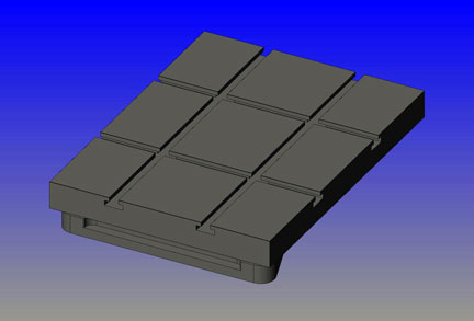
We offer two standard versions of the top platform. The first is six inches by six inches (152 by 152 mm) by one-half inch (13 mm) thick. It has 24 holes drilled and tapped in the top surface, that will accept one-quarter inch (1/4", 0.25", 6.35 mm) by twenty threads per inch, screws. These holes are spaced 1.0" inch apart. This forms a very versatile way for clamping objects on the table. The top surface of this platform is ground flat. There are additional 1/4"-20 holes for the adaption KP-6-6-T.
The second version of the top platform is 6 inches by 6 inches (152 by 152 mm) by one half inch (1/2", 0.5", 12.7 mm) thick. It has no holes in the top surface, and it is intended for custom installations where a tailored mounting method is used. It is part number KP-6-6-P. If preferred, we will bid machining the mounting apparatus that you need, to your specifications. The top surface of this platform is ground flat. This second version is considerably less expensive than the pre-drilled and tapped design.
Bottom Platform
There are two standard versions of the bottom for the 6" X 6" Kinematic Platform. The conventional design consists of a rugged six inch by six inch (6" X 6", 152mm X 152mm) by one-half inch (1/2", 13 mm) thick aluminum plate. A shallow relief is machined on the bottom of the plate to leave three one and one-half inch (3 1/2", 89mm) square pads, that provide a stable location against the mating structure. A one-quarter inch diameter (1/4", 6.3 mm) counterbored hole, is drilled through the center of each pad so the bottom can be rigidly clamped down with one-quarter inch or 6mm socket head cap screws. Three pieces of three-quarter inch (3/4", 19mm) diameter, high-precision spheres are glued into three symmetrical recesses in the top surface of this platform (part number KP-6-6-CS).
The second standard version of the bottom consists of three rigid bars of aluminum that are one inch (1", 25.4 mm) wide by four inches (4", 101 mm) long and one-half inch (1/2", 12.7 mm) thick. A high precision three-quarter inch (3/4", 19mm) diameter ball is glued into a recess at one end and a one-quarter of an inch (1/4", 0.25", 6.4 mm) wide by three-inch (3", 76 mm) long, recessed slot is machined through the bar.
This allows the three spheres attached to these bars to be adjusted and clamped down from a wide pattern of one-quarter inch (1/4", 0.25", 6 mm) threaded holes. These three bars can also be clamped to tee-slots in the mating structure. In addition to the three bars we also supply a fourth bar with a five-eighths of an inch (5/8", 0.625",16 mm) diameter hole, with 18 threads per inch, through one end to hold our super strength rare-earth magnet (see the following paragraphs. It has the same three inch long hold, part number KP-3-BAR.)
Also available is Part number KP-MG-BAR is also available to hold a powerful magnet for preloading the Kinematic Platform.
Sub-Plates
Sub-plates are available for the 6" × 6" pre-assembled kinematic platform. These inexpensive sub-plates are the full 6 inch by 6 inch (152.4 mm by 152.4 mm) and are three-eighths inch (9.52 mm) thick, part number SP-6-6. They are precision ground flat and parallel. There are three counter sunk, one-quarter inch (1/4", 0.25", 6.3 mm) diameter holes, that exactly match the hole pattern in the drilled and tapped top platform (our part number KP-6-6-T).Three flathead screws are supplied with each sub-plate, for attachment.
This inexpensive sub-plate (our part number SP-6-6) has a plain flat upper surface that can be custom tailored.
Vertical Mounting
An additional feature of the 6 × 6 Kinematic platform is that it can be used in a vertical position for light loads, if it is adequately pre-loaded.
6 × 6 Kinematic Platform Pricing
| Part # | Description | Price | Purchase |
|---|---|---|---|
| KP-6-6-P | KINEMATIC PLATFORM, 6" X 6", PLAIN TOP PLATE | $80.30 | |
| KP-6-6-T | KINEMATIC PLATFORM, 6" X 6", DRILLED AND TAPPED TOP PLATE | $105.00 | |
| KP-6-6-CS | KINEMATIC PLATFORM, 6" X 6", BASE PLATE WITH SPHERES | $64.90 | |
| KP-3-BAR | KINEMATIC PLATFORM, THREE-BAR PLATFORM BASE | $74.80 | |
| SP-6-6 | KINEMATIC PLATFORM, 6" X 6", SUB PLATE | $20.90 | |
Magnetic Preload
| Downloads | |||
|---|---|---|---|
| Part # | Solidworks | IGES | |
| 625-18-HPD | |||
| 625-18-MG-N | |||
| 625-18-MG-S | |||
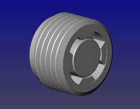
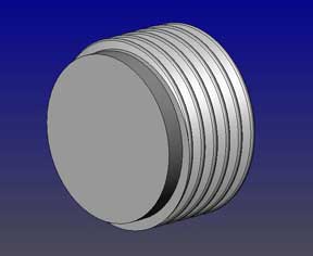
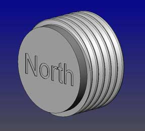
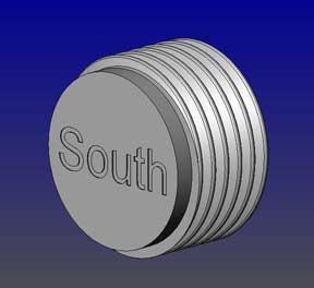
To add versatility to this platform, we offer an optional magnetic pre-loading arrangement. Both top and bottom platforms have a five-eighths of an inch (5/8", 0.625", 15.9mm) by 18 threads per inch hole tapped through the center that will accept our standard five-eighths of an inch (5/8", 0.625", 16 mm) diameter 18 threads per inch adjustable super magnets, Part Number 625-18-MG-N or 625-18-MG-S. This design is far superior to embedded naked magnets or a high magnetic permeability plug, Part number 625-18-HPD. The magnetic preload kit, Part number 625-18-MG-KIT, includes two magnets: one north-seeking, and one south-seeking, and also a high magnetic-permeability plug.
The beauty of this design is that the magnetic pre-load can be used or not used. If it is used, it can be adjusted from one ounce to 14 pounds (6.4 kg). For a heavy pre-load, use two super rare-earth magnets. There is a north-seeking magnet in one platform, and in When no magnetic pre-load is desired, the Kinematic platforms are used without the magnets. This design is far superior to embedded naked magnets.
Advantages of Magnetic Pre-Load
- The first advantage is that you can use the magnets or not, depending on your requirements.
- The second advantage is the adjustability of the magnetic force. By using a north seeking magnet in one platform and a south seeking magnet in the other, large magnetic forces, up to fourteen pounds (14 lb., 6.4 kg), can be generated. By adjusting the separation of the magnets, this force can be attenuated or tuned to give a small fraction of this value.
- The third advantage is that when a much smaller force is needed, a high permeability disk (part number 625-18-HPD), can be substituted for one of the magnets thus cutting the original attraction in half. Using this arrangement, forces of just an ounce (1 oz, 30 g) can be achieved.
- The fourth advantage is that our five-eighths inch (5/8", 0.625", 16 mm) diameter adjustable magnets are well-shielded so that there is almost no stray magnetic leakage floating around.
- The fifth advantage is that the magnetic pull exerted between the two platforms is axiomatic, thus pulling the two platforms together with perfect symmetry. The magnetic pre-load kit (our part number 625-18-MG-KIT) includes one north-seeking magnet, one south-seeking magnet, and a high permeability plug.
There are four slots in the top face. This allows adjustment up and down by rotating it with a special Spanner Wrench, Part Number SW -1.
Magnetics Pricing
| Part # | Description | Price | Purchase |
|---|---|---|---|
| 625-11-MG-N | MAGNETICALLY PRELOADED KINEMATIC COUPLING, NORTH | $27.08 | |
| 625-11-MG-S | MAGNETICALLY PRELOADED KINEMATIC COUPLING, SOUTH | $27.08 | |
| 625-18-HPD | HIGH MAGNETIC PERMEABILITY PLUG | $10.58 | |
| 625-18-MG-KIT | MAGNET PRELOAD KIT, INCLUDES N/S MAGNET, PLUG | $61.38 | |
Mechanical Clamping for Kinematic Applications
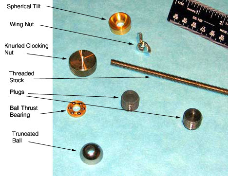
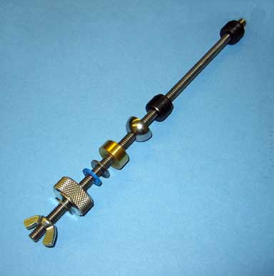
A mechanical clamping technique has been developed for this platform so that it can be used in off axis, high load or, fail-safe, This mechanical clamping kit consists of a 5/8-inch (0.625", 16 mm) diameter plug with 18 threads per inch, on the O.D., (part number 625-250-PLUG) screws into the center hole in the bottom platform. It has a 1/4-inch (6.3 mm) by 20 threads per inch, center hole to accept a length of continuous threaded stock. A similar plug with a .280-inch (7.1 mm) diameter clearance hole, part number 625-280-PLUG, screws into the top platform. A rather long piece of continuous threaded stock passes through this hole and through a self-aligning spherical tilt, part number 75-ST-270. This spherical tilt is used to isolate any X-Y-Z misalignment of the clamping force. It also includes a ball thrust bearing which decouples the torque of the clamping and a truncated ball. The entire assembly is tied together by a one-inch (1", 25.4 mm) diameter, knurled clocking nut (part number 250-20-CN). This stainless steel clocking nut includes a wing nut and washer to be used as a jam nut under conditions of moderate vibration. The entire kit, including all of the parts required, is part number KP-CLAMP.
Spring Load
When a spring-loaded force is preferred, for pre-loading, a very simple arrangement will suffice. By just inserting a spring of the desired stiffness between the clocking nut and the spherical tilt or between the bottom of the spherical tilt and the platform, the job is complete.
Custom Versions
Custom versions of this 3" × 3" platform will be quoted. The platforms can be supplied, hard anodized or nickel-plated, and or with reference surfaces flat lapped. The same basic design can be built with cemented tungsten carbide, kinematic components that will give greater load carrying capacity, higher resonant frequency and more accurate repeatability. It should also be noted that cemented tungsten carbide components will carry very heavy loads, with no sign of fretting.
Flexures
Many customers use the Kinematic Platform with flexures. See the next section below.
Mechanical Clamping of Kinematic Couplings, Mechanical Pre-Loading of Kinematic Couplings
There is a very simple mechanical clamping technique for use on kinematic couplings that can be used for fail-safe, high load carrying, off axis loading and vertical kinematic couplings. This approach is very viable in high vibration environments.
The Pre-Load Kit
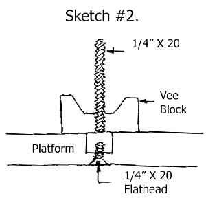
The design consists of all of the components required for the Kinematic coupling as well as those for the clamping system. The system uses three of our standard, cylindrical post-mounted vee blocks (part number 75-VB-CBM) [3 pieces required] mounted on the bottom platform. See Kinematic Catalog 105B , for the dimensions and full details. These are used with three pieces of one-quarter inch (1/4", 0.25", 6.35 mm) by 20 threads per inch, continuous threaded stock. This threaded stock projects up through the top of the Kinematic platform and down through the bottom platform.
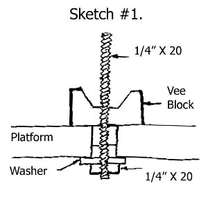
Above the vee block, the 1/4"-20 continuous threaded stock passes through a clearance hole in the upper three quarter inch ( 3/4", 0.75", 19 mm) diameter Kinematic sphere (our part number 75-270-CH) [3 pieces required] and on through the top platform. The two Kinematic platforms are held rigidly together by a one-inch (25.4 mm) diameter knurled clocking nut (our part number 250-20-CN) [3 pieces required]. This device is supplied with a heavy washer and a wing nut, to lock the clocking nut, for use in moderate vibrational environment. When situations of severe vibration are encountered a special clocking nut, fitted with our barn door clamping system may be required. Please contact our engineering department. This device includes a ball thrust bearing which decouples the torque of the clocking nuts rotation. This nut transfers the clamping force through a self-aligning three quarter inch (19 mm) diameter spherical tilt (our part number 75-ST-270) [3 pieces required]. The clocking nut has a timing line engraved on the face, so that the applied force can be repeated, by simply clocking the position of this engraved
A complete set of the Kinematic coupling hardware and the mechanical clamping kit, with all three sets of the components is available as (our part number FS-KIT-750). An advantage of using this clamping technique is that a much higher clamping force can be applied because three screws are utilized instead of one. These three clamps are placed far out towards the edges of the platform, leaving the center of the platform for mounting the payload.
The mechanical stability of the three-clamp platform is much better, because the clamping force is applied as far out as possible. The downside to this design is that there are four lose pieces of hardware that must be assembled for each clamp.
Bottom Mount
The mechanical clamp can be mounted so that the clamping screw projects out the bottom side of the platform. This leaves the front face clear of any protrusions that would interfere with mounting the payload. If the end of the clamping assembly is obscured by this inverted mounting, it may be advisable to use a hex “jam nut” instead of the usual wing nut supplied.
Clamping Small Platforms
On small platforms, a single clamp, located in the center of the platform may suffice. Using only one clocking nut with one spherical tilt and a single piece of 1/4-20 continuous threaded stock, located in the exact center of the Kinematic coupling good results may be achieved. (our part numbers 250-20-CN and 75-ST-270).
Spring Loading
Spring-loaded clamping may be desirable in some special applications. When this option is used it is only necessary to add a spring of the proper rate and a washer between the clocking nuts and the spherical tilt, or between the bottom of the spherical tilt and the top platform.
Summary
The complete three piece set of Kinematic coupling hardware and the three-element fail-safe Kinematic clamping kit is available as (our part number FS-KIT-750). It consists of the following:
- Three pieces of (our part number #75-VB-CPM), the cylindrical post mounted vee block. See page 19 of our Kinematic catalog 105B for design details.
- Three pieces of (our part number 75-270-CH), which is the three quarter inch diameter Kinematic sphere with a .270-inch (6.86 mm) diameter center hole. See addendum to catalog 105B.
- Three sets of (our part number 75-ST-270), the three-quarter inch (19 mm) diameter spherical tilt.
- Three pieces of our one-quarter inch (6.35 mm) by 20 continuous threaded stock that are 9 inches (229 mm) long. You can cut these extra long pieces to the desired length when you make the assembly.
- Three pieces of one-quarter inch (6.35 mm) by 20 threads per inch heavy duty hex nuts.
- Three pieces of heavy duty machine washers, one inch (25.4 mm) O.D. by one-quarter inch (6.35 mm) I.D.
- Three pieces of a one-inch (25.4 mm) diameter knurled clocking nut (our part number 250-20-CN) including the ball thrust bearing, a washer and a wing nut.
- Three pieces of screwdriver slot-one quarter inch (6.3 mm) by 20 flat head screws by three quarter inch (19 mm) long that are used if the alternative method (shown in sketch #2) is used to clamp the vee block to the bottom platform.
12" × 16" Kinematic Platform
The 12 inch by 16 inch (304 mm by 406 mm) Kinematic Platform is a well-established design with years of successful use. This seasoned design is rugged, but at the same time it is lightweight. A high stiffness is achieved through an integral ribbed structure. The cast aluminum design provides good damping and high stiffness. The top platform is one and one half inches (38 mm) thick but weighs only 16 pounds, (7.2 kg). The overall height from the bottom of the bottom platform to the top of the top platform is three and one quarter inches (3 1/4", 82.6 mm). The Kinematic couplings used on this platform are of a high load carrying design. It uses three spheres of three quarter inch ( 3/4", 19mm) diameter on the bottom and three cylindrical vee's on the upper plate. The three spheres are not ordinary steel bearing balls; but are ultra fine grain, high chrome, high carbon stainless steel that is hardened to 58 HRC minimum and precision lapped to AFBMA instrument quality grade 10. Standard steel bearing balls used in competitive products are prone to rust and are very susceptible to fretting, which is one of the major problems of Kinematic couplings.
The Kinematic couplings in the top platform consist of three pair of one-half inch (1/2", 12.7 mm) diameter cylinders that form three vees. These cylinders are securely glued into three precision-machined trenches, with a ceramic filled epoxy, that has a 3000-pound per square inch (535 kg per square cm) shear strength. These cylinders are made of exactly the same material and processed in the same manner as the precision balls. After hardening, these cylinders are ground and precision lapped to a surface texture that is below one microinch (25 nm) Ra. This contrasts with competitive products that use commercially ground only dowel pins, made of carbon steel that is prone to rust and very susceptible to fretting. There are two standard versions of the 12"-16" top platforms. It is available with a plain flat top surface, so that our customer can provide any custom mounting facilities they desire; or we will bid machining the mounting features to your blue print or rough sketch. The top surface of this platform is ground flat. This plain configuration is the least expensive. It is part number KP-12-16-P.
Top Platform
The top platform is also available in our standard breadboard configuration with four precision machined tee slots that use standard three eighths of an inch (3/8") or M10 Tee-nut hardware. This arrangement allows an infinite variety of mounting configurations. The top surface of this platform is ground flat. This is part number KP-12-16-S.
| Downloads | ||
|---|---|---|
| Solidworks | IGES | |
| N/A | ||
| Downloads | ||
|---|---|---|
| Solidworks | IGES | |
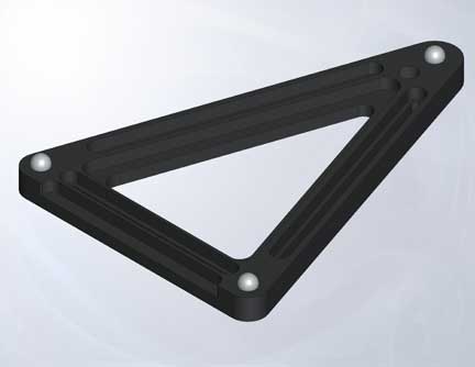
There are also two standard versions of the bottom platform. The first version of the bottom platform is built in a rugged triangular configuration. There are three slots that run the length of each leg of the triangle, that will accept either three eighths of an inch or M10 socket head cap screws, for holding this platform to its mounting surface. There is also a recessed ridge around the inside and outside rim of the triangle that will facilitate the use of hold down clamping.
The second standard version of the bottom platform consists of three separate, one and one half inch (1 1/2", 38 mm) wide, by one inch (1", 25.4 mm) thick, by five-inches (5", 127 mm) long bars. Each bar has an instrument quality, grade 10, sphere rigidly mounted on one end and a four inch long recessed slot, that will accept a three eighths of an inch or M10 socket head cap screw to hold it down. This set of 3 pieces is part KP-3-BAR.
With a symmetrical light load, the 12-16 platform can repeat in all six degrees of freedom within 4 microinches (0.1 micrometers). This platform will carry up to 100 pounds (45 kg) of load safely.
Mechanical Hold-Down
The substantial weight of the top platform, at 16 pounds (7.2 kg), usually precludes the need for additional preload; there are, however, circumstances that do require it.
Vertical Mounting
With its very rugged construction this platform lends itself to vertical or even upside down mounting. The facility for mechanical pre loading is built right into the design of the 12-16 Kinematic platform. A special version of the three quarter inch (3/4", 19 mm) diameter spheres used in both versions of the bottom platforms can have a one-quarter inch (1/4", 6.4 mm) diameter clearance hole drilled through them. The three quarter inch (3/4", 19 mm) diameter Kinematic sphere with clearance hole drilled through it is (our part number 75-270-CH). Three of these
Then a one-quarter inch (1/4", 6.3 mm) by 20-threaded hole is drilled and tapped below these spheres. There is a one quarter inch (1/4", 6.3 mm) diameter clearance hole drilled through the top Kinematic platform that allows a piece of continuous threaded stock to screw into the bottom platform and pass up through the top platform. When mechanical clamping is used, it is important to isolate all of the potential X-Y and Z axial errors to prevent any cocking tendencies when the clamping force is applied. This is done by incorporating a spherical tilt between the clamping force and the top of the platform. This spherical tilt is (our part number 75-ST-270). The full mechanical clamp requires three. The clamping force to hold the two platforms together is provided by three, one-inch (1", 25.4 mm) diameter knurled clocking nuts, (part number 250-20-CN). These clocking nuts include a ball thrust bearing that decouples the torque generated by tightening these nuts. A wing nut and washer are supplied to be used as a jam nut, under conditions of moderate
The clocking nut is a one-inch (1", 25.4 mm) diameter knurled, stainless steel device, with a clocking line engraved on the top face, so that the clamping force generated by tightening it can be repeated time after time. This clamping force will have a major effect on the "Z" axis position as well as the pitch and roll of the top platform.
Note: If mechanical clamping is going to be required, it must be ordered at the time the platform is purchased.
Spring Loading
Spring-loaded clamping may be desirable in some applications. When this option is used, it is only necessary to add springs of the proper rate and washers between the clocking nuts and the spherical tilts or between spherical tilt and the platform. A 12-16 Kinematic platform that is provided with mechanical clamping can be converted back to a simple platform by just unscrewing the three pieces of 1/4-20 continuous threaded stock. The complete mechanical clamping kit, with all three sets of components, installed on the platform is part number 12-16-FS-KIT-750. Additional information on mechanical clamping of Kinematic couplings may be found in the addendum to our Kinematic Catalog 105B.
Custom Versions
Other features, such as hard anodize, nickel plated surfaces, or precision flat lapped reference surfaces can be supplied on special order. This Kinematic platform can be supplied with cemented tungsten carbide component parts that will give higher load carrying capacity, a higher resonate frequency and much better repeatability. The top platform can also be supplied with a pattern of drilled and tapped holes of either English or metric diameter to suite the customer's requirements.
Kinematic Platform Pricing
| Part # | Description | Price | Purchase |
|---|---|---|---|
| 250-20-CN | KNURLED CLOCKING NUT | $20.90 | |
| 250-20-TD | SCREWS FOR KINEMATIC PLATFORM TIE DOWN KIT | $18.70 | |
| 3DBP12X16 | THREE DIMENSION BALL PLATE, 12" ( 30 CM ) X 16" ( 41 CM ) | $2750.00 | |
| 625-11-MG-N | MAGNETICALLY PRELOADED KINEMATIC COUPLING, NORTH | $27.08 | |
| 625-11-MG-S | MAGNETICALLY PRELOADED KINEMATIC COUPLING, SOUTH | $27.08 | |
| 625-18-HPD | HIGH MAGNETIC PERMEABILITY PLUG | $10.58 | |
| 625-18-MG-KIT | MAGNET PRELOAD KIT, INCLUDES N/S MAGNET, PLUG | $61.38 | |
| 625-18-MG-N | MAGNETIC PRELOAD KIT, NORTH | $27.08 | |
| 625-18-MG-S | MAGNETIC PRELOAD KIT, SOUTH | $27.08 | |
| 625-20-MG-N | MAGNETICALLY PRELOADED KINEMATIC COUPLING, NORT | $27.08 | |
| 625-20-MG-S | MAGNETICALLY PRELOADED KINEMATIC COUPLING, SOUTH | $27.08 | |
| 625-250-PLUG | PLUG FOR MECHANICAL CLAMP, BASE PLATE | $13.20 | |
| 625-280-PLUG | PLUG FOR MECHANICAL CLAMP, TOP PLATE | $13.20 | |
| 75-ST-270 | SPHERICAL TILT, 3/4" DIAMETER | $35.20 | |
| CR-625-18-MG-N | MAGNETICALLY PRELOADED KINEMATIC COUPLING, NORTH | $36.19 | |
| CR-625-18-MG-S | MAGNETICALLY PRELOADED KINEMATIC COUPLING, SOUTH | $36.19 | |
| CR-625-HPD | MAGNETICALLY PRELOADED KINEMATIC COUPLING | $19.80 | |
| KP-12-16-CS | KINEMATIC PLATFORM, 12" X 16", BOTTOM TRIANGLE | $136.00 | |
| KP-12-16-P | KINEMATIC PLATFORM, 12" X 16" PLAIN TOP PLATE | $163.00 | |
| KP-12-16-S | KINEMATIC PLATFORM, 12" X 16" TOP WITH T SLOT | $183.00 | |
| KP-3-3-CS | KINEMATIC PLATFORM, 3" X 3", BASE PLATE WITH SPHERES | $53.90 | |
| KP-3-3-P | KINEMATIC PLATFORM, 3" X 3", PLAIN TOP PLATE | $79.20 | |
| KP-3-3-P-3BAR | KINEMATIC PLATFORM, FIVE PIECE SET, PLAIN TOP PLATE AND A THREE BAR PLATFORM BASE | $154.00 | |
| KP-3-3-P-CS | KINEMATIC PLATFORM, TWO PIECE SET, 3X3 PLAIN TOP PLATE AND 3X3 BASE PLATE | $122.00 | |
| KP-3-3-T | KINEMATIC PLATFORM, 3" X 3", DRILLED AND TAPPED TOP PLATE | $101.00 | |
| KP-3-3-T-3BAR | KINEMATIC PLATFORM, FIVE PIECE SET, WITH A THREADED TOP PLATE AND A THREE BAR PLATFORM BASE | $176.00 | |
| KP-3-3-T-CS | KINEMATIC PLATFORM, TWO PIECE SET, 3X3 THREADED TOP PLATE AND 3X3 BASE PLATE | $140.00 | |
| KP-3-BAR | KINEMATIC PLATFORM, THREE-BAR PLATFORM BASE | $74.80 | |
| KP-4-HEAVY-BAR | KINEMATIC PLATFORM, 12" X 16", BOTTOM FOUR PIECE BAR SET | $97.90 | |
| KP-6-6-CS | KINEMATIC PLATFORM, 6" X 6", BASE PLATE WITH SPHERES | $64.90 | |
| KP-6-6-P | KINEMATIC PLATFORM, 6" X 6", PLAIN TOP PLATE | $80.30 | |
| KP-6-6-T | KINEMATIC PLATFORM, 6" X 6", DRILLED AND TAPPED TOP PLATE | $105.00 | |
| KP-6-6-T-CS | KINEMATIC PLATFORM, TWO PIECE SET, 6X6 THREADED TOP PLATE AND 6X6 BASE PLATE | $169.00 | |
| KP-CLAMP | KINEMATIC PLATFORM, COMPLETE CLAMPING KIT | $82.50 | |
| SP-3-3 | KINEMATIC PLATFORM, 3" X 3", SUB PLATE | $18.70 | |
| SP-6-6 | KINEMATIC PLATFORM, 6" X 6", SUB PLATE | $20.90 | |