Bal-tec™ Home Compliant Mechanisms
Compliant Mechanisms
Compliant mechanisms for engineering applications can be very effective. To comply is to yield or bend. These mechanisms should be accordant, that is, they should bend or yield without failing, rupturing or permanently upsetting. All movement should remain within the elastic realm.
The advantages of compliant systems over conventional hinges and bearings are numerous. There is absolutely no back lash or end play in these structures. There is no friction and no hysteresis. There are practically no speed limits, outside of inertia itself, as their performance extends well into the kilohertz range.
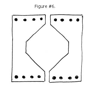
On top of all this, compliant systems are inexpensive and can have almost infinite life expectancy without ever needing lubrication. A bellows would be a prime example of a compliant mechanism. See Figure #1.
It will yield at least somewhat in all degrees of freedom except yaw, in which it is extremely rigid. This need for rigidity introduces a new element to the engineering concept of compliance. For a system to be useful for engineering applications, a compliant mechanism should be entirely rigid within the physical limits of the materials involved in at least one degree of freedom.
Another feature of a compliant mechanism is that its movement should be uniform. In some design applications it should define a perfectly linear motion while in others it should depict a perfectly rotary motion.
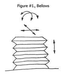
As all compliant mechanisms actually produce a rotary motion, it is quite complicated to turn this into an acceptable linear movement. What is referred to as a four bar mechanism is the first functional approach to doing this. The moveable platform, in this linear mechanism, is connected to the fixed element of the system by four leafs or reeds of flexible material. When a deflecting force is applied to the movable platform, it will be displaced through the bending at eight points of compliance. Using this approach, the movable platform will translate along a linear path; however, it will also dip slightly. See Figure #2.
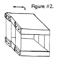
Correcting this dip requires an even more complex mechanism. By adding an additional four bar compliant mechanism below the movable platform and directing the actuation to this platform, the upward movement of this platform will exactly compensate for downward dip of the top movable platform. The output will be a very linear straight line. See Figure #3.
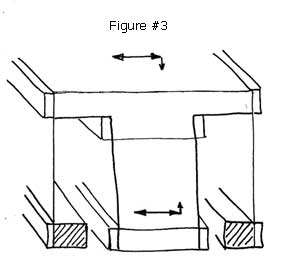
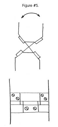
Generating pure rotary motion using compliant mechanisms requires similar auxiliary additions, as the simple bending motion between two rigid bodies is easily deflected in multiple directions. Without providing crossed or restricting compliant elements, the rotary motion will be polluted with parasitic, off axis movements. See Figure #4
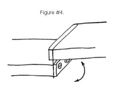
The crossed reed technique provides multiple compliant elements positioned at right angles to each other. See Figure #4 and #5. The additional right angle stiffening by the additional compliant elements provides extremely accurate rotary motion.
Compliant mechanisms may seem too good to be true, but they too have their limitations. The linear and rotary motion provided by compliant mechanisms have very limited travel, in order to achieve high load carrying capacity, the stiffness or spring rate goes off the scale. This is driven by the fact that the spring rate or stiffness varies as the square of the thickness. Doubling the thickness will quadruple the stiffness. It is of interest that the spring rate varies directly with the width and inversely with the length. The wider the stiffer and the longer the more flexible.